Strength and fatigue analysis in Simcenter 3D 2206

An efficient setup gives you the right answers at your fingertips
Strength and fatigue analysis has historically been the domain of the specialist. Over the years, these specialists created tools to make everyday tasks easier. Therefore, it is not uncommon for young engineers to have a learning phase. During which they spent familiarizing themselves with the tools available within their organization. They often discover a labyrinth of quagmires with incomplete documentation and commands that can only be run on the command line, when completed in the correct order, and in the predetermined file location.
Meet Isambard
Simcenter 3D has been working hard to connect software packages and improve the support material of the products joining the Simcenter 3D family. So let us consider the case of young Isambard, a fresh-faced graduate in his first position after university. Like most engineers in his company, young Isambard is designing bridge parts that are safety-critical components. He knows from previous experience that it is insufficient to show a plot of the stresses when his manager asks for proof. The manager will want to know what these stresses mean with respect to the material and how safe the design is.
The status quo
Like many companies, Isambard’s has an in-house legacy tool that translates stresses for a given material into safety factors, so he gets to work. He post-processes the stresses to find the maxima, and he creates the correct equivalent stress to put in the tool. Isambard checks that he has the same material selected in both his finite element analysis and his stress tool. Many of these steps require manual work, and a lot of manual work is often the source of errors.
Young Isambard can quickly get this far without mistakes, he is destined to be a great engineer after all. Finally, he puts his values into a report and gives it to his manager. This would be the end of his task in an ideal world, and he could take a well-deserved coffee break. However, this is just the beginning, his manager returns and asks, “what happens in this other notch? What happens if you change the radius here?”… And the list went on.
“Oh Boy,” Isambard thinks, “there was nothing I wanted to do more today than repeat that whole process again.”
Isambard’s dream for strength and fatigue analysis
As he walks back to his desk, he dreams of a world where these tasks are automated, and software packages share information without the laborious steps. Like all great engineers, his mind wonders as it tries to find a way to make his tasks more efficient. Finally, he remembers that he is using Simcenter 3D as his finite element environment and wonders if it has a fatigue tool that can automatically do some of these steps. Perhaps, it could even update after changes are made to the finite element results. “That would be great,” he thinks. As he walks, he wonders, “perhaps I should try it, but would I need complex fatigue material data to use it? And can I create a process that reduces the amount of work I need to do when my boss comes back with more questions?”
He decides to break down his tasks and requirements into crucial steps to answer these questions.
Strength analysis can be:
Pure static – i.e., compare a local stress/strain value with a threshold
Infinite life based – i.e., no fatigue
Combined
How do I ensure static safety, and what tools can help me?
Isambard knows that the simplest way to ensure strength is to derive them from the company’s internal guidelines. These guidelines define a load case that can be modeled in finite elements with some maximum allowable stresses for different materials. This is why he chose this approach with simple finite element post-processing previously.
However, he wants to answer his manager’s questions and anticipate what questions will come next. He knows that when a guideline is designed to compare equivalent stresses that the standard post-processing does not provide, several questions arise:
- How do you explain a stress plot to management who wants to know how much safety is still in the design?
- How do you compare different materials in your structure with varying strength values?
- What do you do if the guideline defines a strength value that is not included in the material data of your finite element analysis?
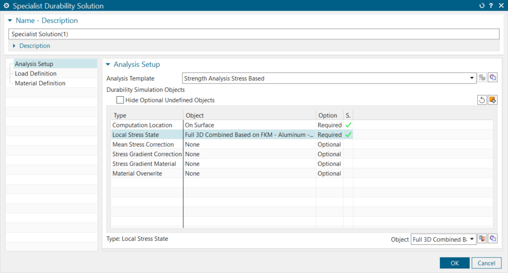
He decides to play with a workflow in Simcenter3D Durability to see if he can find easy and robust answers.
Create a simple event:
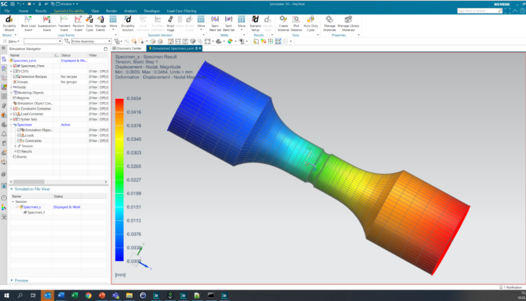
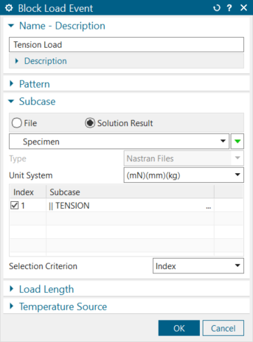
With a Simcenter 3D Block Load Event, Isambard knows he can easily use the finite element study results and even scale the study’s results if required. So he opens up the Block Load Event tool and starts building his test for his tensile load case.
The process starts by adding all the necessary information (unit systems, subcase names, etc.), however, fortunately for Isambard, this is automatically taken into account when using a Load Event for strength analysis, so in a blink of an eye, he has all the information added. Perhaps he won’t be spending all day doing this after all.
Now he can start to create a durability test. Ordinarily, this would have taken Isambard an excessive amount of time. However, the extra time that Isambard has spent playing with the Simcenter 3D package has enabled him to discover the predefined Strength Analysis templates.
A center for support is just a few clicks away
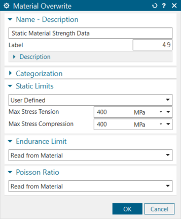
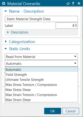
Previously, Isambard used the predefined case from a guideline for an aluminum material type for the equivalent stress and tried to consider the material’s ductility. This was because the material in his finite element analysis had no strength data added. Isambard can see this may be a problem but is unsure what to do. He decides that his best option is to search Support Center for a solution. While searching, he comes across an article on ‘Defining the Walker damage parameter without a stress-strain relation.’ In the document, he sees a tool called ‘Material Overwrite’ that can create a user-defined Poisson’s ratio and even read the Poisson’s ratio from the material properties. To his relief, he discovers that he can add the strength data to the material definition of his finite-element study.
Since Isambard wants to predict his manager’s future questions, he reviews the other input options. He finds a lot, from the load situation of the test data to the temperature influences and even survival probability. He can’t help but think to himself, “if I can plot these results onto pretty graphs that even a politician can understand, I may actually finally get that coffee break.”
Solving for strength and fatigue
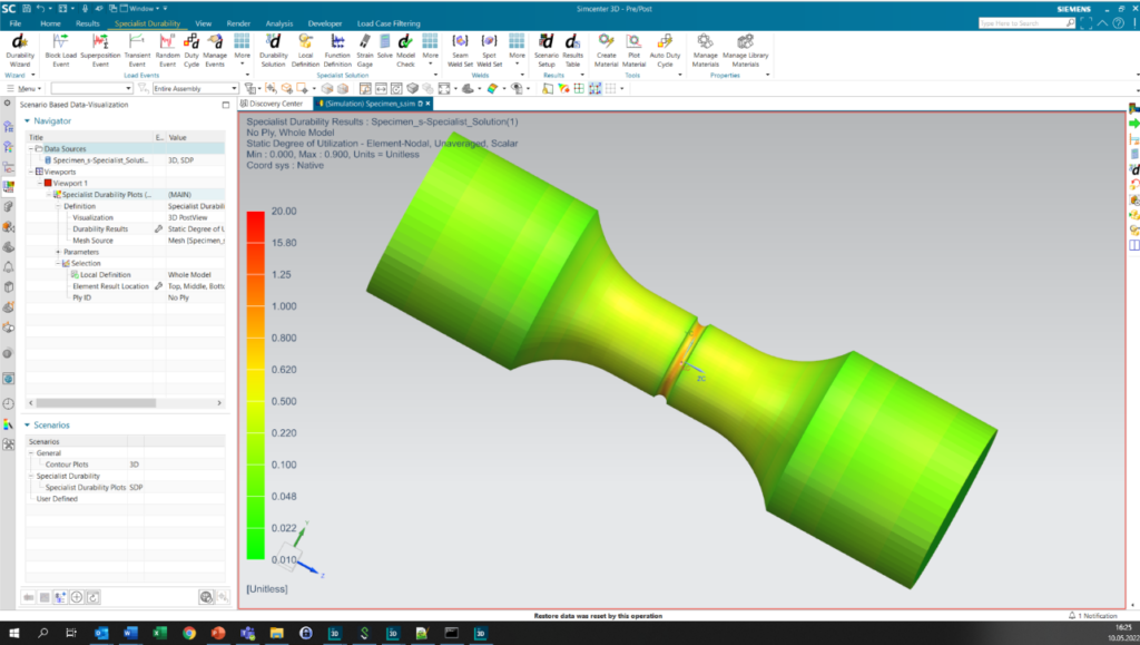
The first result Isambard gets is the overview in the result table. This result is the same as when he used the approach with an in-house code, but now the values are automatically taken from the most critical point, and the correct equivalent stress is used. However, this was not Isambard’s reason for using Simcenter 3D. He wants results that even the least technical customer has a chance of understanding, then his manager should be happy.
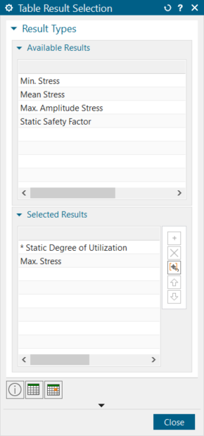
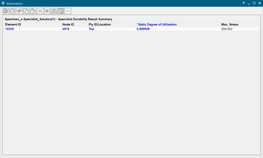
From Support Center documentation, Isambard knows that he is not limited to just the results that he manually created before. With Simcenter 3D, he has full post-processing possibilities, such as contour plots and safety factors.
This new integrated workflow allows him to include a strength analysis in any finite analysis run. The time spent reading stresses and filling in values in external tools, then creating tables can now be used to improve his structure and compare different designs.
New load cases
Isambard’s manager asked him to consider how loading the design in different ways would affect the results. Just the thought of this fills Isambard with dread, “Surely I won’t have to redo all this work every time my manager has an idea, I will never see the end to this project.”
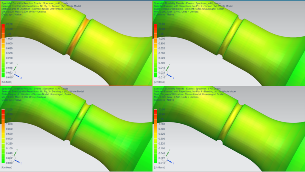
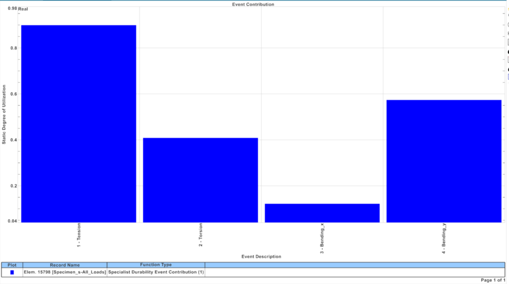
Fortunately, this is Isambard’s lucky day. One of the advantages of his workflow is the lack of restriction to a single load case. He can simply add more load cases, like torsion and bending, combine them into one load duty cycle, and analyze them in one strength analysis. This allows the software to automatically find the most critical load case and create results for the maximum degree of utilization of all load cases.
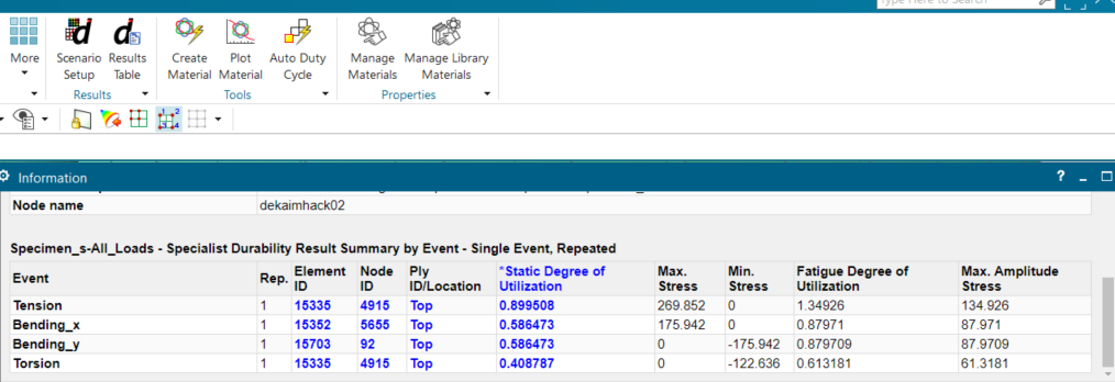
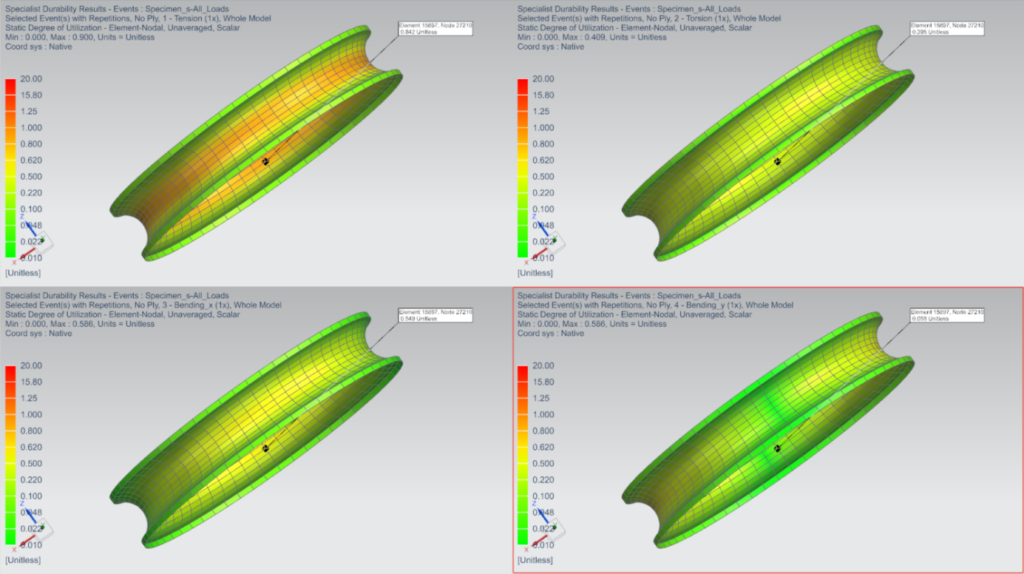
The tool can also superimpose the different load cases, such as in phase, out of phase, and many other combinations. It can even use real load histories from a load prediction using multi-body analysis or from test data.
Isambard may not have realized it initially, but an important advantage of using the durability set-up is that it updates the mesh after re-running the finite element analysis. As a result, he only needs to define scaling and superposition once. After updating the finite element analysis, he can re-run his strength analysis, and all the results automatically update for the new design.
Strength and fatigue analysis of transient runs
Having completed the static investigation, he now moves on to fatigue analysis. With things going so well in Simcenter 3D, he decides to continue with this tool. For a complete load scenario at each point in the structure, one needs the largest and the smallest equivalent stress value that builds the enveloping load cycle. This load cycle is necessary to get the fatigue strength. A durability analysis can provide this in the same way as the previous strength analysis. To avoid making a mess of his files, Isambard starts with an example. He analyzes a rim for which he has calculated the stress values at every 10° step of rolling it.
For this scenario, he needs to use the Transient Event to reference the finite element results, but he finds this easy to select in the software. He can do everything else in the same way as for the static load. Below we can look into the Fatigue Degree of Utilization that he generated.
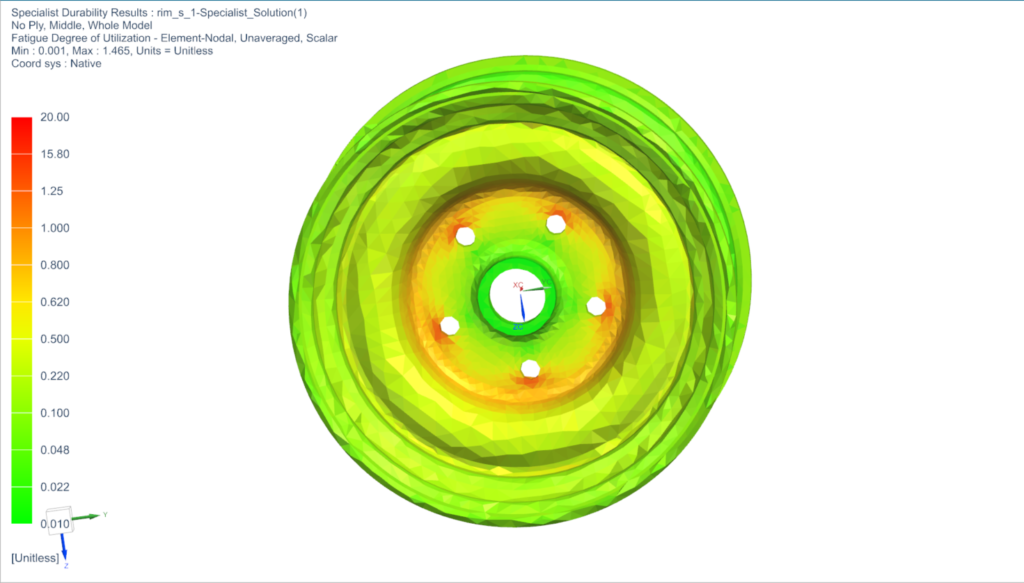
He can see some fatigue degree of utilization above one around the bolt holes, but overall, he is happy that he can get the kind of results he needs. This technique, he realizes, will be beneficial for other non-linear finite element analyses. Like the previous bolting example, where a pre-stress is required, other finite element analyses could investigate effects such as repeated loads on the fatigue strength or even effects of changing temperatures. “yes!” he exclaims, “With Simcenter 3D, I can analyze multiple cases with one analysis.”
Conclusion – Strength and fatigue analysis in Simcenter 3D Durability
The strength analysis case provides static and fatigue strength analysis for any finite element set-ups created in Simcenter 3D. Furthermore, the user benefits from Simcenter 3D’s full integration of finite element and fatigue workflows.
You can use material data from a material database (inherited from finite element analysis) or directly in the analysis case.
It provides the needed information (safety factors, degree of utilization, plus load information on the local stress values).
Simcenter3D makes strength and fatigue analysis easy and robust, and Isambard may be getting a raise this year.
Related blog posts
Simple and fast access to strength and durability insights
Thermal fatigue: some hot features in Simcenter 3D Durability