Powering data centers with gas turbines – Why System Simulation matters

AI-demand makes the energy bottle neck critical
AI-driven data centers, with their insatiable appetite for electricity, are reshaping energy infrastructure. Gas turbines are uniquely positioned to address these challenges. Unlike intermittent renewables, they provide dispatchable power, ensuring 24/7 reliability for data centers. For instance, Tesla’s Colossus xAI supercomputer facility in Memphis relies on 35 on-site gas turbines to support its 200,000 GPU operations. That’s why the industrial gas turbine market is expanding rapidly, driven by both demand and innovation.
Indeed large-scale AI training clusters can require hundreds of megawatts of firm capacity while exhibiting highly variable load profiles driven by GPU utilization cycles, cooling systems, and workload scheduling. Unlike conventional data center loads, AI factories present a fundamentally new challenge: stochastic, high-frequency power fluctuations superimposed on large sustained demands that must be matched by generation assets in real time.
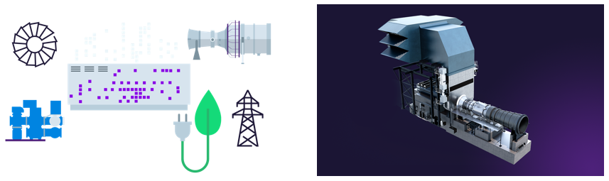
Using parallel gas turbines to power AI data centers creates an islanded microgrid setup. Placing multiple aeroderivative or heavy-duty gas turbines side-by-side allows operators to scale power output dynamically to match extreme computational demand.
While much attention is given to the gas turbine itself, the real challenge lies in optimizing the entire energy ecosystem: balancing power generation, battery storage, grid interaction, and highly variable AI demand.
This is where Simcenter Amesim provides a decisive advantage. Through multi-domain system simulation, engineering teams can evaluate, optimize and validate the data center architectures with their power generation with gas turbines before building the hardware implementation onsite.
Why AI workloads challenge power grids
Events like GPU training campaigns or large inference workloads bring start-up and shut-down sequences. Unlike traditional web hosting with predictable diurnal curves, AI compute loads experience massive step-change transients due to differing workload dynamics. It creates both predictable and stochastic power variations that the energy system must accommodate.

| AI workload | Electrical profile | Impact on microgrid |
| GPU training | Massive sustained load with sudden synchronized steps when batches start, fail, or checkpoint. – Periods: 100 ms to 30 s | Causes severe grid frequency drop if thousands of GPUs step up simultaneously. |
| Inference & prompts | Highly stochastic, bursty load spikes based on user traffic and context length. – Duration: 50 ms to 1 s (prefill phase) or Seconds to Minutes (decoding phase) | Requires immediate spinning reserve capacity to prevent voltage sags. |
| Agentic AI loops | Multi-step reasoning loops causing sustained, unpredictable multi-node power spikes. Duration: Minutes to Hours | Prevents turbines from operating at steady-state sweet spots, dropping thermal efficiency. |
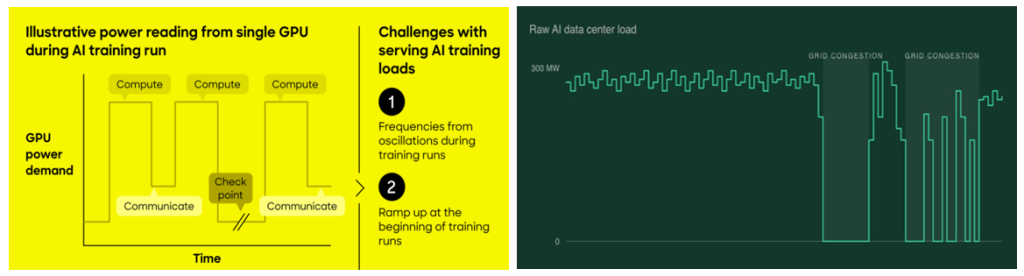
That’s why designing the appropriate gas turbines to match such AI load profiles is key. While it has a direct impact on the operations, control and cooling aspects.
- Start / Stop / Restart sequences:
- Frequent starting and stopping shortens hot-section component life due to thermal fatigue (1 start can equal 10–20 operational hours of wear).
- Cold restarts take too long to absorb sub-second AI power jumps. As a result, turbines must run in spinning reserve (idle at high fuel consumption) or rely on Battery Energy Storage Systems (BESS) to bridge the transient response gap (50–500 ms) while turbines ramp up.
- Control strategy:
- Traditional closed-loop PI controllers react too slowly to microsecond GPU switching. Control architecture requires Feed-Forward Predictive Control, where the AI cluster’s scheduler signals the turbine control system (TCS) milliseconds before dispatching heavy GPU workloads.
- Cooling system distribution:
- Liquid cooling loops (CDUs and chillers) mirror the electrical load transient. If GPUs drop load rapidly, cooling demand plummets. Turbines running on combined-cycle mode (using waste-heat recovery boilers) experience thermal mismatches, risking heat exchanger shock or cooling fluid boiling.
Let’s investigate how to manage these requirements thanks to the digital twin in Simcenter Amesim. We’ll consider here the SGT-800 gas turbine by Siemens Energy, while it could be any other types of gas turbines (smaller, larger) by any gas turbine manufacturer worldwide. The Simcenter tool is very flexible and can adapt to any possible configuration in few minutes with few clicks.
Why the Siemens Energy SGT-800 gas turbine
The Siemens SGT-800, with a nominal electrical output of approximately 47.5 MW, is well suited to support medium and large AI data centers.

For facilities requiring several hundred megawatts, multiple gas turbines can be deployed in parallel to provide scalable and resilient power generation. Rather than treating each turbine as an isolated asset, data center operators increasingly need tools to evaluate how multiple generation units interact with variable AI workloads, Battery Energy Storage Systems (BESS), utility grid connections, cooling infrastructure or microgrid controllers.
This system integration perspective emerged as a key requirement during discussions on future data center energy architectures. Such simulations create value for OEMs, system integrators, energy providers, and data center operators.
A digital twin of the SGT-800 gas turbine applied to Data Center needs, can help explore key questions such as:
- When should additional turbines be started?
- What are the impacts of cycling on turbine lifetime?
- How can operating costs be minimized?
- How should power be sourced between turbines and the grid?
Digital twin for presizing in Simcenter Amesim
Let’s see how Simcenter Amesim is accelerating gas turbine development with System Simulation.
The steady-state model was first sized using the “Gas turbine performance tool”, which is a built-in feature of Simcenter Amesim. It allows selecting the right architecture to directly generate in few seconds the system layout with all its components well connected.
The workflow starts with the selection of the gas turbine architecture — in this case a single-spool turboshaft configuration — and the definition of the main datasheet characteristics required to establish the on-design operating point.
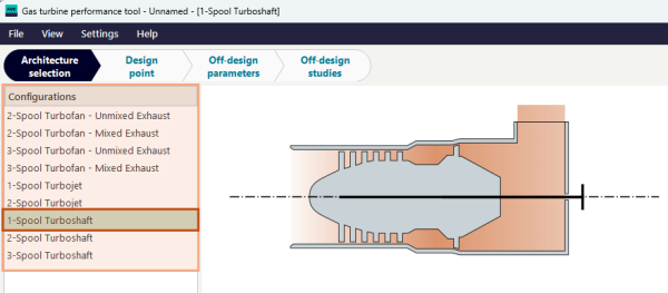
We consider here a single-spool turboshaft configuration used as the basis for the SGT-800 static sizing. Then we’ll get the nominal performance characteristics used to establish the reference operating point. Once the on-design point is defined, the tool performs batch calculations across a range of off-design operating conditions.

This makes it possible to check the gas turbine operating envelope at several load levels, typically from 90% to 105%, and to verify how the machine behaves under different ambient and operating-point assumptions.

The HP compressor map and the HP turbine map are used to visualize the corrected mass flow, pressure ratio, efficiency trends, and the operating envelope before generating the complete Simcenter Amesim model. After the sizing and the envelope checks are completed, the “Generate Sketch” button automatically creates the corresponding Simcenter Amesim gas turbine model.

The complete gas turbine model is now generated with its predefined parameters. It’s prepared for the next step of its integration with the auxiliary systems around: the drivetrain, the generator, the AI computing load, and the controllers for the different subsystems. Well done! It only took a couple of minutes to get this great achievement. Let’s now move to the next step to get the dynamic model for the full transients of the digital twin.
Dynamic model for transient analysis
The dynamic model extends this architecture with shaft inertias, clutch and gearbox dynamics, fuel-control loops, start-up sequencing, droop governor behavior, and a stochastic data-center AI computing load profile to evaluate the transient response and power tracking.

The model comprises three interconnected subsystems:
- The thermodynamic core: “Inlet Guide Vane” compressor (SAE maps, 6-species gas mixture: N₂, O₂, Ar, CH₄, CO₂, H₂O), primary combustion zone (CH₄ fuel, LHV = 47 MJ/kg, η_comb = 99.95%), and high-pressure turbine.
- The drivetrain: HP shaft inertia (J₁ = 1000 kg·m², AI-assisted), main clutch, gearbox (ratio Ngen/Ngg_nom = 1500/6600), generator-side inertia (J = 14000 kg·m², AI-assisted), rotary spring-damper coupling.
- The control & Load: PID fuel controller, droop governor, starting sequence state machine, and the stochastic data-center demand model.
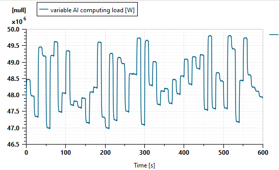
Rather than attempting to simulate the AI algorithms directly, the data center grid connection is represented as a stochastic power demand signal composed of two mathematical components:
- A random component for the short-term fluctuations
A uniformly distributed random signal r(t) representing the unpredictable GPU load switching events. This captures the fast, non-deterministic nature of the AI workload bursts on a 10-second scheduling horizon.
- A harmonic component for the periodic grid interactions
Three sinusoidal terms model the periodic load cycles driven by the cooling demand, the batch job scheduling, and the thermal management cycles. The combined signal passes through a first-order lag filter (τ_DC = 0.5 s) before being fed to the droop governor, preventing the turbine fuel system from reacting to the instantaneous spikes.
A hierarchical control strategy, fully effective thanks to AI
The gas turbine should not directly follow every fluctuation of the AI load. Instead, a hierarchical control architecture is required. It comes with different layers and their own controllers.
- Layer 1: Gas Turbine Dynamics: At the lowest level, the SGT-800 model represents the compressor dynamics, the fuel system behavior, the combustion process, the shaft speed and the electrical power generation
- Layer 2: Turbine Unit Controller: Each turbine contains its own control functions. It’s available for start-up sequencing, speed regulation, load control, temperature limitations and protection systems. The objective is to ensure safe and efficient operation while tracking power setpoints provided by higher-level controllers.
- Layer 3: Plant Supervisory Control: The supervisory controller manages a fleet of turbines. For example, a 300 MW facility might operate 6 units × SGT-800 of 47.5 MW ≈ 285 MW installed capacity. Its key responsibilities include unit commitment, load sharing, start/stop decisions, reserve management and availability optimization. This approach becomes particularly relevant as the recent AI campuses deploy multiple gas turbine units operating in parallel.
The control strategy comes with a droop governor and PID. It’s actually the classical droop strategy combined with a cascade PID fuel controller. The droop governor adjusts the fuel flow setpoint based on the generator speed error, preventing the turbine from chasing every micro-fluctuation of the stochastic data-center demand:
ΔP_setpoint = P_nom · (−1/R) · (N_act − N_nom) / N_nom [R = 5 % droop]

A 5 % droop (R = 0.05) means a 5 % speed deviation produces a 100 % power response — providing isochronous-like behavior under the operating range. The downstream PID then drives the fuel valve to meet the corrected fuel flow setpoint, with output saturation to prevent compressor surge or over-temperature. Some dynamic switches sequence the control loops during start-up, self-sustain, and rated-power phases.
It is worth mentioning that the AI assistant in Simcenter Amesim played a significant role in sizing and tuning several key parameters that would otherwise require extensive iterations or experimental data. It was key to succeed and to get the first results quickly.
| Parameter | AI-Suggested Value | Physical Rationale |
| Global Control Architecture | 4-layer hierarchy | AI proposed layered: turbine PID → droop governor → supervisory switch → DC load filter |
| Starting Sequence Timing | t₁=1 s, t₂=30 s, t₃=90 s, t₄=30 s | Lightoff → self-sustain → rated speed ramp; inspired by SGT-800 commissioning data |
| PID Gains (Kp, Ki) | 4.0 / 0.5 | Proportional-integral gains tuned via AI for robust fuel control response with 5 % droop |
| Power Demand Equations | Harmonic + random model | AI recommended 3-frequency harmonic + stochastic random superposition to mimic AI GPU load profiles |
| Generator Inertia J | 14 000 kg·m² | Generator-side inertia; reflects typical 47 MW class synchronous machine |
| HP Shaft Inertia J₁ | 1 000 kg·m² | Turbine-side rotational inertia; sized for stable speed dynamics during load transients |
Parameterization is greatly enhanced thanks to the AI Assistant of Simcenter Amesim
Well done, we now have our complete SGT-800 gas turbine with its control strategy and subsystems around. The engineering teams can start investigating any types of runs corresponding to various scenarios.
Simulation results for the full start-up sequence
It’s now time to look at the great achievements we can get from this digital twin of the SGT-800 gas turbine in Simcenter Amesim. The model runs over a 600-second transient simulation capturing the full start-up sequence followed by the rated-load operation under stochastic data-center demand.
Let’s check first the power tracking results. At top-left, we can see the generator output vs. data center power demand [MW]. At top-right, we plot the fuel flow rate [kg/s] with the starter & grid-connection commands. At bottom-left, there’s the generator loading [%]. And at bottom-right, we can see the GG (gas generator) speed [rpm] and the net gas power [MW]. The start-up transient is well visible during the 0–150 s period; while we can see the droop-controlled steady state thereafter.

Everything is under control, well done! Let’s now move to other key quantities to look after to ensure the gas turbine operates properly for the different operating points during the transient phase. We extract the relevant information, from left to right, for the compressor, turbine and exhaust. At the bottom, the graphs show respectively the surge margin & pressure ratio for the compressor, the air mass flow rate for the turbine) and the heat flow rate and the temperature of the combustor.

We can finally check the information for the compressor and turbine regarding their operating lines within their maps.

There’s the compressor map (left) with its surge line, iso-speed lines (70–105 % corrected speed), and simulated operating line. While we have the turbine map (right) with its corrected mass flow vs. pressure ratio iso-speed lines and operating line at the design conditions. Both maps use the SAE-format performance data from the Simcenter Amesim “Gas Turbine Engine” library.
Takeaways – A successful deployment from day 1
This SGT-800 model demonstrates a viable system-level simulation framework for evaluating gas turbine operations in AI data center environments. The results show that the start-up sequence, droop control, and PID fuel governor work together to track a stochastic AI computing demand well representative of the GPU workload patterns.
Simcenter Amesim enables engineers to identify the best technology for gas turbines to power AI Data Centers, drastically reducing physical prototypes. So it contributes to delivering the appropriate systems for power generation to operate successfully onsite from day 1. The ROI (return on investment) reducing the design iteration, development cycle and commissioning is massive.
The real innovation is not the gas turbine alone, but the ability to simulate and optimize the complete AI data center energy ecosystem
Going further – So many possibilities with such a flexible framework
Since the digital twin of your gas turbine for Data Centers is now ready, it’s only benefits exploiting it to leverage its intrinsic power and to increase your productivity on relevant use cases. The are many nice next steps to investigate. For example, we can list some first ideas here:
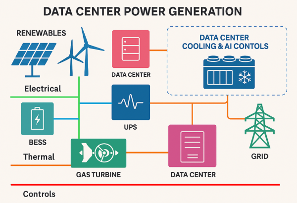
- ⚙️ Consider the N gas turbines in parallel to get the full power generation. Either duplicating the single gas turbine model which runs in 12 seconds of CPU-time for 600s of simulation, or replacing it with an even faster ROM (reduced order model) in case hundreds of runs are needed.
- 🔋 Investigate hybrid configurations to manage the slow and fast variations of the AI computing load. Typically evaluating Battery Energy Storage System (BESS) in AI-powered facilities rather than forcing the gas turbines to react to every power fluctuation. The fast variations are handled by the battery while the slow variations are managed by the gas turbines.
- ♻️ Consider complementing the power generation with renewables like solar panels or wind turbines. With its “Energy Management System” (EMS) at the highest level to coordinates the gas turbines, batteries, renewables sources and grid connection. Also to minimize the operational costs.
- 💧 Investigate alternative fuels like hydrogen (H2) for the gas turbine instead of methane (CH4). Sustainable fuels are alternatives to traditional fossil fuels that can significantly reduce carbon emissions. It can also be hydrogen derivatives such as ammonia (NH3) and methanol (CH3OH) for decarbonizing gas turbines and supporting the transition to a more sustainable energy future.
- 💰 Explore the techno-economic assessment of the complete microgrid with gas turbines and controllers to compute the energy cost under realistic scenarios, up to weather conditions, OPEX/CAPEX metrics or predictions of the CO2 emissions.
Learn more about Siemens Simcenter Amesim
Simcenter Amesim is the leading integrated, scalable system simulation platform, allowing system simulation engineers to virtually assess and optimize the performance of mechatronic systems.