How modular simulation reduces EV thermal management complexity

Welcome to the first part in a six-part series, demonstrating the importance of robust model management in the creation and deployment of a systems simulation model.
This article explains how the adoption of a modular simulation approach to model development, through the definition of a system model architecture and adoption of Siemens Systems Simulation, can improve model re-use and reduce development time.
The future of mobility is electric, and at the heart of every efficient Electric Vehicle (EV) lies a sophisticated thermal management system. It’s far more than just keeping the battery cool; it’s a complex dance involving the HVAC (Heating, Ventilation and Air Conditioning) and cabin environment, power electronics, the battery itself, and the overall vehicle dynamics. Each domain presents unique engineering challenges, and integrating them into a single, comprehensive simulation model can be a monumental task.
Unless you’re a seasoned expert across all these specialized fields, building and validating such a complex model from scratch can be overwhelming. So, how do leading engineers tackle this intricate problem? The answer lies in a structured, modular simulation-based approach.
Component-based architectures manage EV thermal model complexity
The first step is to strategically define the necessary models or components. The efficiency gain comes from leveraging existing expertise and reusing validated assets.
For illustration, let’s consider a simplified system architecture broken down into four core components:
- HVAC & Cabin: Responsible for maintaining optimal passenger comfort and managing thermal loads within the vehicle interior.
- Thermal Management System (TMS): The central orchestrator, directing heat transfer through pumps, valves, heat exchangers, and other critical components.
- Vehicle and Electrics (incl. Battery): Encompassing the propulsion system, E-drive, and the vital battery pack, which is highly sensitive to temperature fluctuations.
- Cooling System: The physical hardware and fluid circuits specifically designed for heat dissipation.
While this component split offers a clear framework, its true power isn’t in its rigidity, but in the harmonization of interfaces between these components. By establishing a clear “interface contract,” we unlock seamless collaboration and extensive reuse of assets across different projects and teams.
Interface contracts enable reusable, validated component models
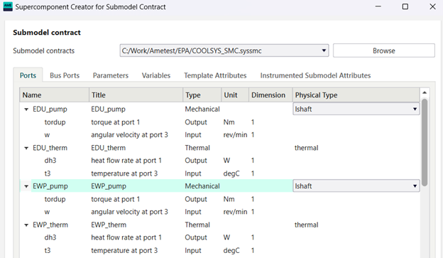
A Model Interface Contract (MIC) is a formal specification that defines how a component model integrates with other system models, including required inputs, outputs, and validation criteria.
What exactly constitutes this interface contract? Think of it as a comprehensive blueprint that meticulously defines the requirements and characteristics of each component model. It should detail:
- Inputs: What specific data, signals, or physical quantities does this component require from other parts of the system?
- Outputs: What information, signals, or physical quantities does this component provide to others?
- Bus Definitions: How are groups of related signals efficiently bundled and managed for streamlined communication?
- Exposed Parameters: Key variables that end-users can easily adjust for conducting parameter studies or adapting the component for specific application scenarios, all without needing to delve into its intricate internal workings.
- Measure Variables: Data points primarily intended for post-processing and analysis, distinct from those directly involved in signal routing or control logic.
Alongside defining these elements, we establish a test cases complete with expected inputs and outputs of the component, or a boundary condition test case.
This test case acts as a rigorous validation benchmark, ensuring the component model performs precisely as anticipated, whether compared against physical test data or a previously validated simulation.
This robust interface definition dictates how a component will integrate and behave within the overall system. It places the responsibility on the supplier (whether an internal modeler or a third party) to deliver a model that is rigorously validated against this contract.
Compared to traditional approaches which place the emphasis on the model integrator, this approach dramatically reduces integration issues and eliminates the need to constantly seek additional information or files, fostering a much smoother development process.
Accelerating development with semi-automated libraries and test harness generation
A significant advantage of this structured approach is the ability to semi-automatically generate libraries and test-case harnesses directly from these interface definitions.
A test harness is a controlled simulation environment that applies specific boundary conditions (inputs like coolant flow rate, ambient temperature, and heat loads) to validate model behavior against requirements
This means:
- The generated harness is immediately executable, ensuring that any component implemented adheres strictly to the contract guidelines.
- Ports, Measure Variables, and Parameters are all automatically populated, saving valuable time and reducing manual errors.
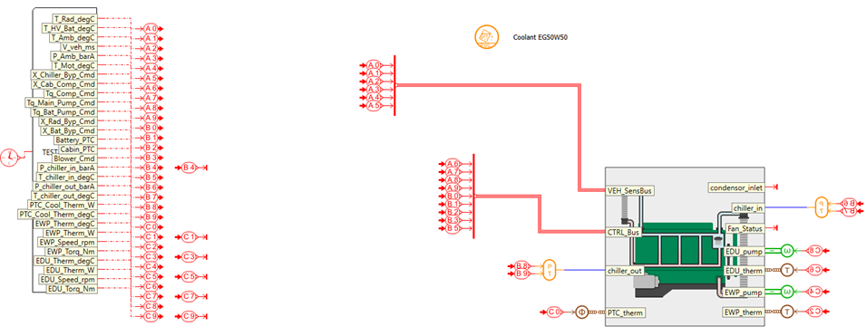
Further by leveraging tools that can import test data and create boundary condition blocks, such as Simcenter Amesim’s Test data import APP, the validation process becomes highly efficient. This allows for rapid iteration and refinement of the test harness model, ensuring it accurately reflects the real-world operational conditions.
Formalizing and validating the Interface Contract
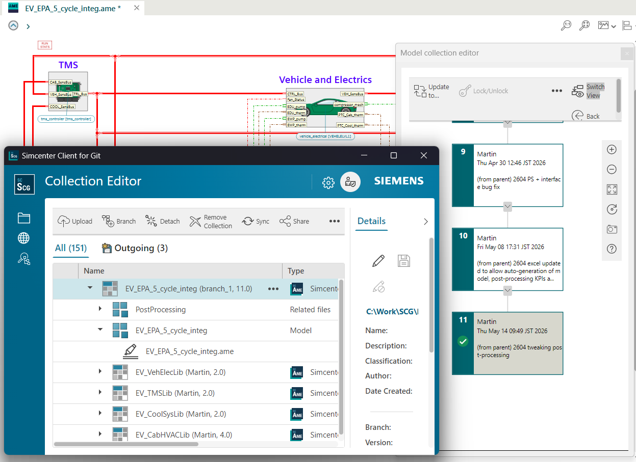
Once the interface contract is formalized and validated, libraries and the validation model are uploaded to Simcenter System Client for Git directly from the Simcenter Amesim user interface. This allows component models (e.g., “EMPTY,” “LVL1”) to be validated entirely separately from both the integrated system model and the final validation model. This capability is essential for collaborative workflows, where multiple team members can work on different aspects without conflict.

Siemens’ “Association” and “Model-based” Collection approach inherently manage these complex relationships between objects, overcoming the impracticality of multiple users simultaneously working on a single binary model file. Here, the validation model, including boundary condition data, becomes the master, meticulously validating each individual component model.
This leads to the creation of common libraries, which can then be seamlessly used across various integrated and individual models. A Simcenter Amesim Library is a collection of standardized re-useable components.
A critical benefit of having models at the component level is the ability to assess execution speed improvements and fixed-step feasibility in isolation, allowing for targeted optimization without impacting the entire system.
Conclusion: Three principles for scalable and modular simulation
By adopting a component-based approach to EV thermal management simulation, engineering teams can manage increasing system complexity without sacrificing speed or accuracy. This methodology delivers three core advantages:
📌Key takeaways
- Interface contracts enable parallel development
- Reusable, validated components reduce rework
- Semi-automated workflows improve efficiency
As EV thermal systems continue to grow in complexity, integrating advanced battery chemistries, multi-mode HVAC strategies, and increasingly sophisticated power electronics, the ability to decompose, validate, and reuse modular simulation components will increasingly separate industry leaders from those struggling with monolithic modeling approaches.
How is your team currently managing component validation across distributed development environments?
In the next blog, we’ll explore how we can use the structured process outlined to automate library template model creation and integration into a system model in a collaborative development environment.