MBST: Simulation Model Validation with Simcenter Testlab 2021.1

With the current push to bring products faster to market and in more variations, we need to rely heavily on simulation models (Model-Based Development approach). It is otherwise impossible to achieve these tight deadlines if you have to wait for the complete physical prototype to be available to run all necessary tests. It means that the validation of these simulation models is essential if you want to be able to trust their results. This is true for simulation models made for any industrial sector such as automotive, aerospace as well as the mechanical industry. No matter how easy or complex your model is, if it has not been validated, you cannot know if the simulation results are reliable.
To do this validation, experimental test data is needed. More than often it must be multi-physical test data due to the nature of modern products. As you already know this multi-physical sensor data can be measured using the Simcenter SCADAS data acquisition hardware and saved to disk using Simcenter Testlab Neo.
So, wouldn’t it be ideal if you could also do this model validation directly in Simcenter Testlab Neo?
This blogpost highlights how to perform validation of simulation models (particularly on Simcenter Amesim models) using the new capabilities in the Simcenter Testlab 2021.1.
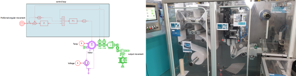
The easiest way to start a simulation model validation is by simply comparing test and simulation time data. This can easily be done in Simcenter Testlab Neo, for example for Simcenter Amesim models thanks to the Simcenter Amesim Sketch Viewer, show in Figure 2.This is a small Simcenter Testlab driver that can be installed in less than a minute and allows accessing Simcenter Amesim model sketches and their simulation results from within Simcenter Testlab Neo with no additional license requirements.
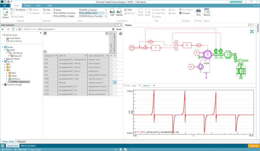
A simple selection of the simulation data can be made with the visual help of the Simcenter Amesim model sketch. All Simcenter Amesim units are supported in the Simcenter Testlab unit system so time-data comparison is easy and painless in your preferred unit system. Also, Simcenter Amesim batch runs are supported, making it seamless to compare your test data to a wide range of simulation runs with varying parameters to find the best match between the two.
To avoid confusion during validation, the Alias Mapping Table can be used to map simulation and test DOF ID’s as they are often not identical.
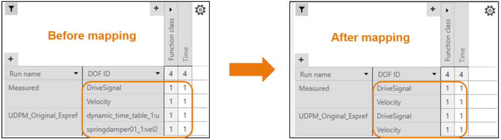
As shown in Figure 3, by using the alias mapping table these DOF ID’s can be linked so that only one common name is shown. This allows easy display of system data (simulation and test) using the wide range of pivot tables and automatic displays available in Simcenter Testlab Neo.
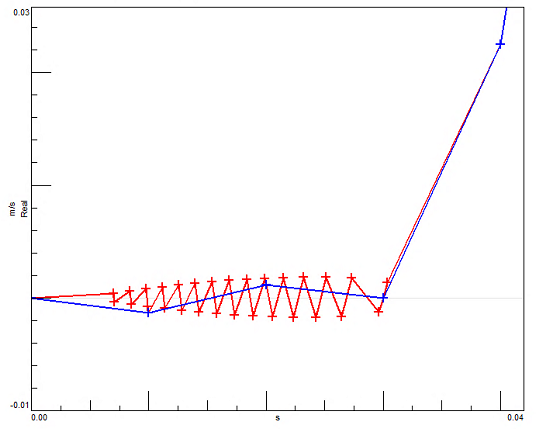
Although your test data has a fixed sample rate (= equidistant data), simulation data is often non-equidistantdue to the widespread use of variable timestep solvers and the presence of system discontinuities. Simcenter Testlab displays support both equidistant and non-equidistant time data. You can therefore see all the simulated system discontinuities in Simcenter Testlab Neo, as shown in Figure 5.
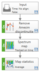
So far, we had a look at comparing simulation and test time data in the Simcenter Testlab displays. But for further validation of your models you also need to compare processed data, for example in the frequency domain, as well as comparing metrics calculated on both simulation and test data. You can do all of this with Simcenter Testlab Process Designer. Most methods in Simcenter Testlab Process Designer only accept equidistant time data due to the nature of the data processing methods. To allow using this non-equidistant data and do your validation based on additional metrics, a new method called “Remove Amesim discontinuities” has been added to Simcenter Testlab Process Designer. This method, followed by some processing is shown in the figure below.
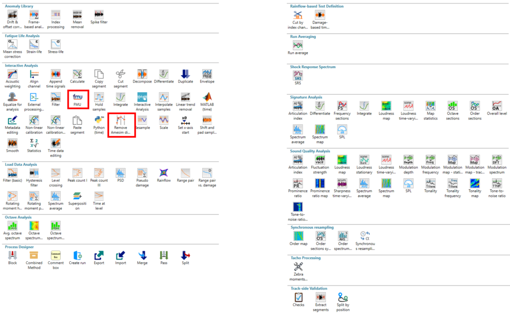
It removes the Amesim non-equidistant data samples thus making this data equidistant. After that, any of the Simcenter Testlab Process Designer methods shown below can be used to process simulation and test data and calculate the required metrics for the simulation model validation.
Up to this point we have discussed how to import Simcenter Amesim results in Simcenter Testlab Neo. This approach works great as long as the data to be exchanged is not bigger than several GBs (~ 4GB). Above this limit, data transfer times hinder the efficiency of the model validation process. Also, in case the simulation models must be fed with many test runs, a different approach is needed for you to remain efficient in the validation process.
So, when exchanging data between simulation and test software is not efficient anymore, you should instead exchange the simulation model directly, embed it in the test software and let it produce the simulation data directly in that environment. When it comes to exchanging simulation models, the format of choice is the FMI standard (Functional Mockup Interface).
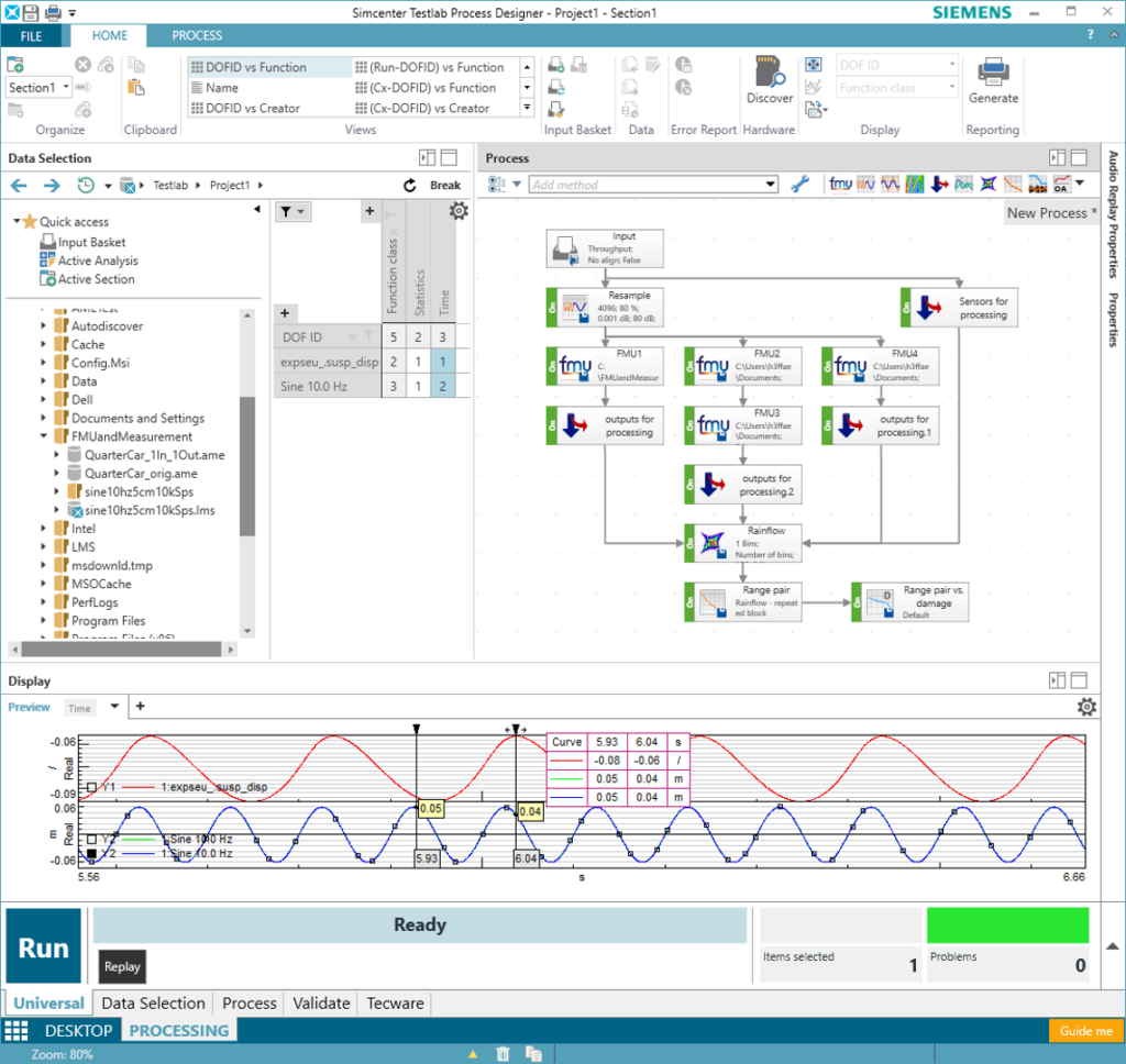
To implement this new validation approach in Simcenter Testlab Neo, you can use the FMU method (Functional Mockup Unit) from Simcenter Testlab Process Designer. Add one or multiple FMU methods to your process, link each method with the FMU of your choice, define which Test run(s) will feed each FMU and you are good to feed GBs of test data into your simulation models and let them produce many GBs of simulation data to be used for validation. Similar to accessing batch runs from Simcenter Amesim, you can execute multiple FMU’s in parallel in one process as shown below.
During this validation process with FMUs, you will of course need to update a few FMU parameters to properly calibrate the simulation model dynamics. To do that, you can manually update these parameters (for those exposed by the FMU) from Simcenter Testlab Neo. So, if you run your process multiple times with different parameter sets you will be doing a simple parameter sensitivity study that will help you in validating your model against test data.
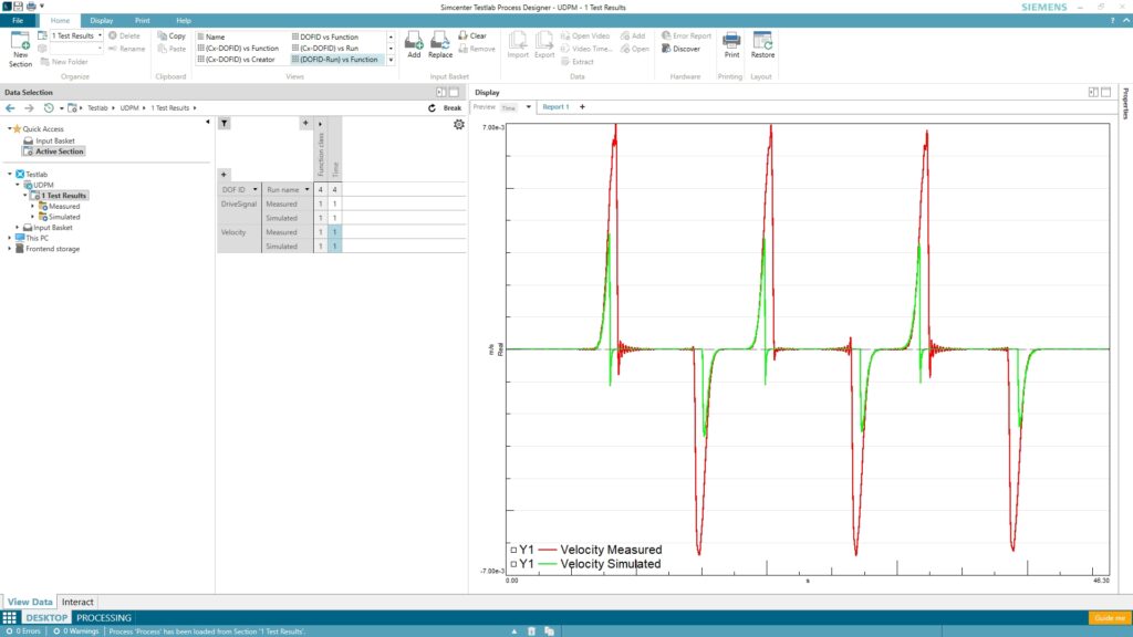
The resulting FMU output data of the model or any explicitly exposed internal variables can directly be compared to the measured test data. You can do this for the raw time data, but you could also continue from here and calculate advanced metrics in an identical way on both the test and simulation data (see Figure 8). This can range from a simple statistical value to the order cut of a spectrum map tracked on a virtual tacho channel from the model. See the rest of the available methods in Figure 7.
Remember: validated simulation models are the key to bring products faster to market. Simcenter Testlab Neo helps you to be productive during the validation of your models.
Going further: the features presented in this blogpost belong to the broader Model-based System Testing (MBST) framework of solutions belonging to the Simcenter portfolio, which aims at closely combining test and simulation for Model-based Development.
To learn more about MBST and simulation model validation, visit our website.