All I want for Christmas is high frequency dynamic mount stiffness data
Selecting the right mounts for integrating a vibrating component is a crucial step in any vehicle NVH development project. But what makes a mount the ‘right’ mount for a given application?
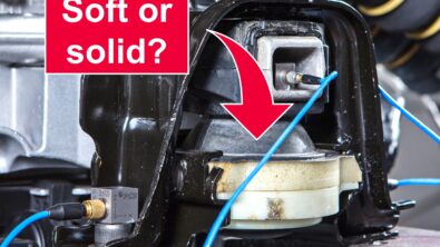
Expert NVH engineers know that the trick is to find the optimal trade-off between isolation and control. Softer mounts absorb more vibrations, but allow more freedom of movement in operation which can lead to other issues. For example, in powertrain integration applications the selected mounts should be soft enough to prevent structural excitations due to combustion, gear meshing or magnetic pole orders from reaching the driver. At the same time, if the selected mounts are too soft then transient torque oscillations can trigger a low frequency tip-in/tip-out motion which increases wear on the bearings and can be felt in the seats and steering wheel.

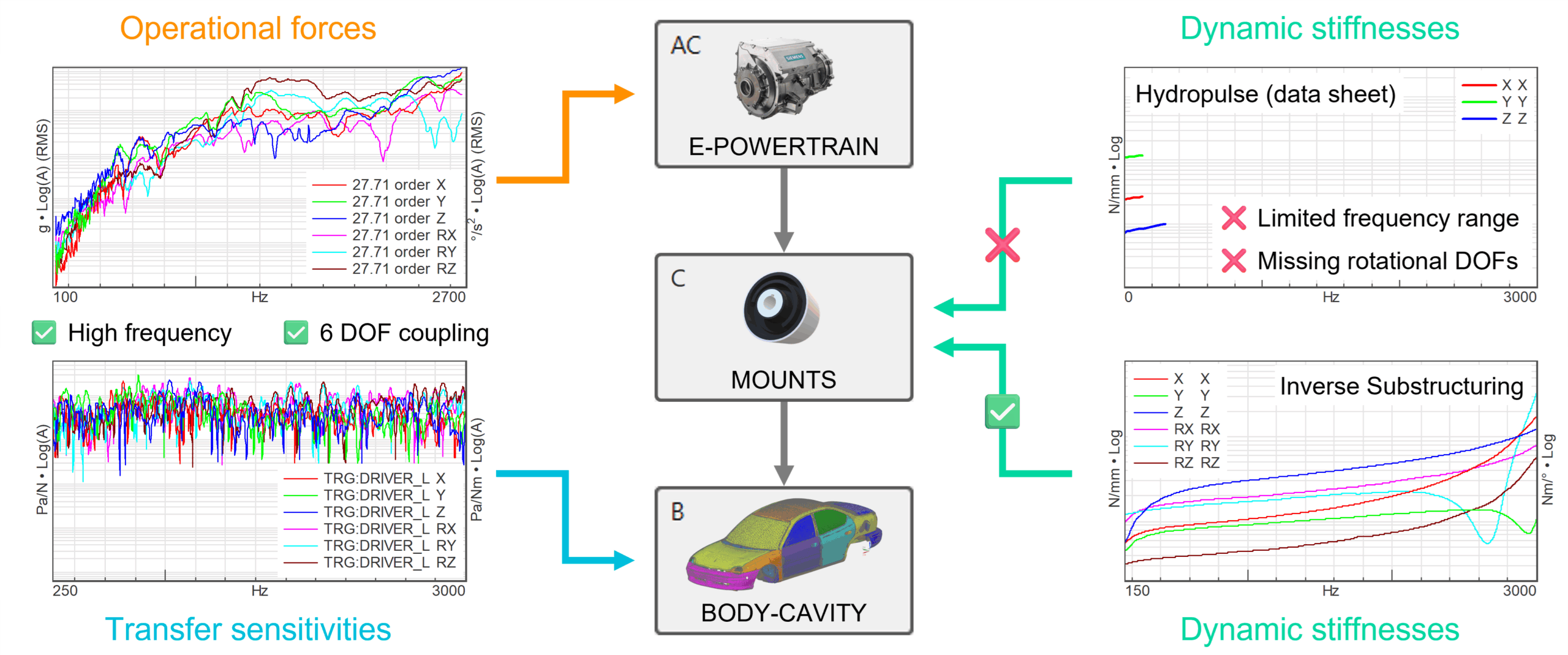
So, how do you find that optimal trade-off then? The secret is knowing the exact dynamic mount stiffnesses at each frequency and coupling Degree of Freedom (DOF) where the structural excitations are significant. For electric powertrains, that typically means up to 2–4 kHz and for all 6 DOFs (translational and rotational) due to the increasingly complex coupling interactions at higher frequencies.
Unfortunately, such high fidelity mount models cannot simply be extracted from a mount data sheet. The dynamic stiffnesses found there are typically obtained on hydropulse test benches, which are limited in frequency range (up to ~500 Hz) and coupling complexity (no rotational DOFs, no cross-coupling).
The solution is to use more advanced techniques such as Inverse Substructuring, which estimates dynamic stiffnesses from Frequency Response Functions (FRFs) measured between the active and passive coupling DOFs of the mount. Since this approach is based on FRF data, the dynamic mount stiffnesses can be obtained up to several kHz and for all 6 coupling DOFs!
Did you know that Simcenter Testlab provides a state-of-the-art workflow for estimating dynamic mount stiffnesses using Inverse Substructuring? Read on and I will show you how to complete the entire process in just 3 simple steps.
Step 1: Virtual instrumentation
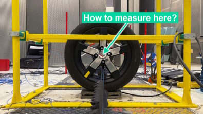
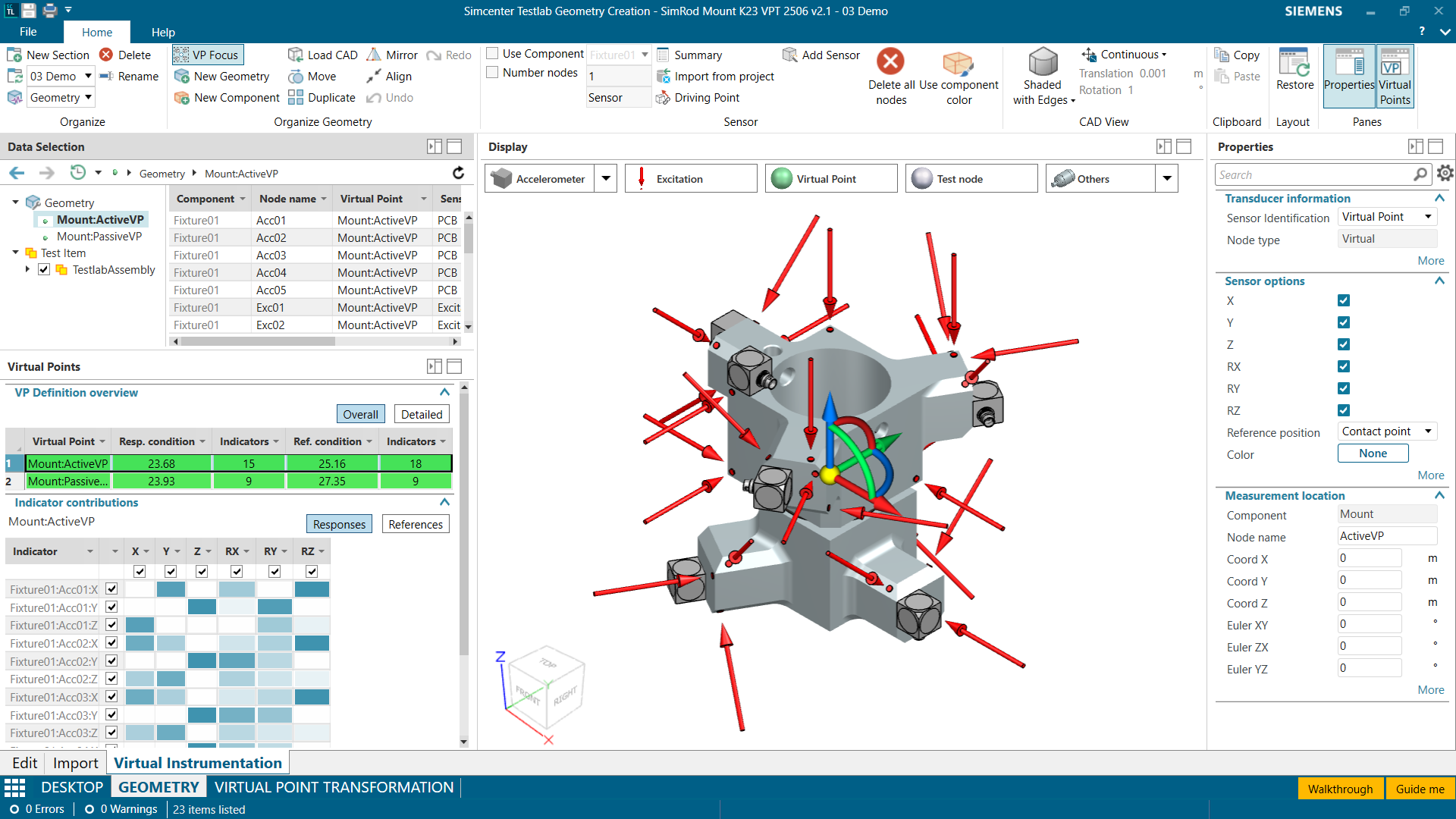
Inverse Substructuring requires an FRF matrix between the active and passive coupling DOFs of our mount. Measuring translational DOFs is straightforward, but including rotational DOFs requires a technique called Virtual Point Transformation (VPT). This is essentially a geometric reduction which transforms an overdetermined set of measured FRFs to a virtual point with 6 DOFs, under the assumption that the structure behaves locally rigid.
To measure the FRF matrix using VPT, we will first define a virtual point at the active and passive sides of the mount. Then, we will attach rigid jigs on the active and passive sides to measure excitations and responses in all 6 DOFs of the virtual points. The actual rigidity of these jigs will be validated using the measured FRFs, and is one of the limiting factors which determine the frequency range of the dynamic stiffness results.

In practice, the easiest way to perform VPT is to prepare a ‘digital twin’ of the instrumentation setup used to measure the FRF data on a virtual geometry in Simcenter Testlab Virtual Instrumentation. This allows us to automate the VPT calculations using highly accurate sensor position and orientation data.
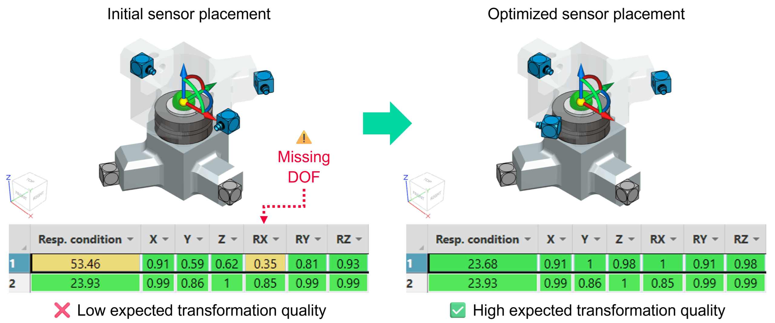
The virtual instrumentation can also be used to optimize the physical instrumentation for VPT before measuring, significantly reducing the risk of costly measurement re-runs. During virtual instrumentation, Simcenter Testlab predicts the expected transformation quality in real-time, allowing the engineer find a smart sensor distribution which maximizes the transformation quality while minimizing the overall measurement effort.
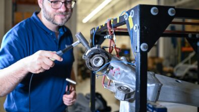
Step 2: FRF testing
Once the instrumentation setup has been prepared and optimized, it’s time to head to the lab for the FRF measurements. If you are using an impact hammer, the new Simcenter Testlab Impact Acquisition workbook offers a highly efficient workflow which is seamlessly integrated with Simcenter Testlab Virtual Instrumentation.
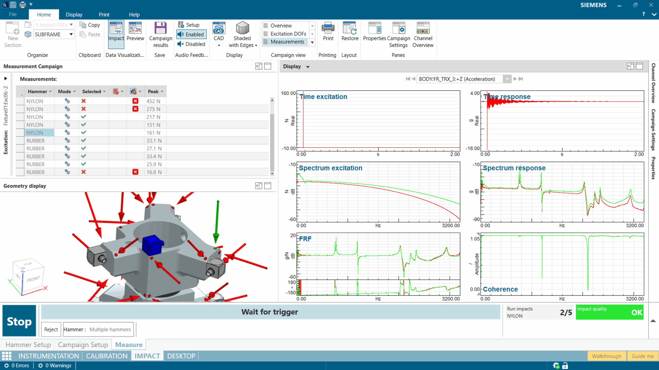
Impact testing is a manual job, which means that each impact will contain a certain amount of noise and uncertainty depending on the skill of the operator. To counter this, Simcenter Testlab’s Smart Hit Selection feature continuously monitors each incoming impact and automatically selects the best impacts which maximize the quality of the averaged FRF results. This feature greatly improves the efficiency and consistency of impact testing across operators.

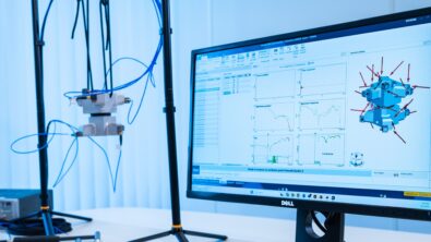
Step 3: Virtual Point Transformation
The final step is to transform the measured FRFs to the virtual points and estimate the dynamic stiffnesses using Inverse Substructuring in Simcenter Testlab Virtual Point Transformation. The only required action here is to define which are the active (input) and passive (output) side virtual points of the mount. Afterwards, all calculations are performed fully automatically by linking the measured FRFs to the virtual instrumentation.
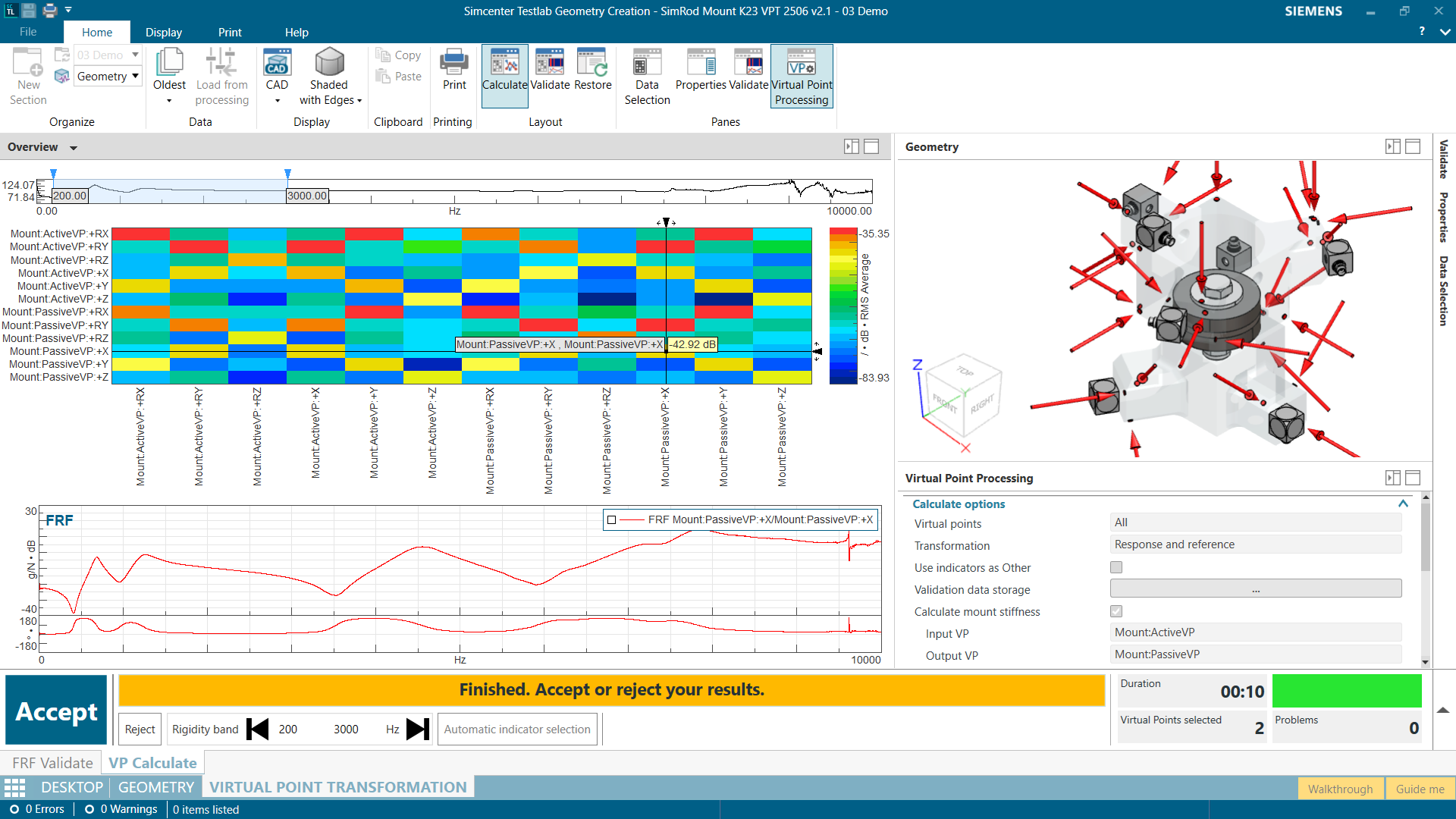
The results can be validated using the rigidity and driving point phase quality metrics, which quantify up to which frequency range the virtual points behave consistently with the assumption of local rigidity and physical plausibility.
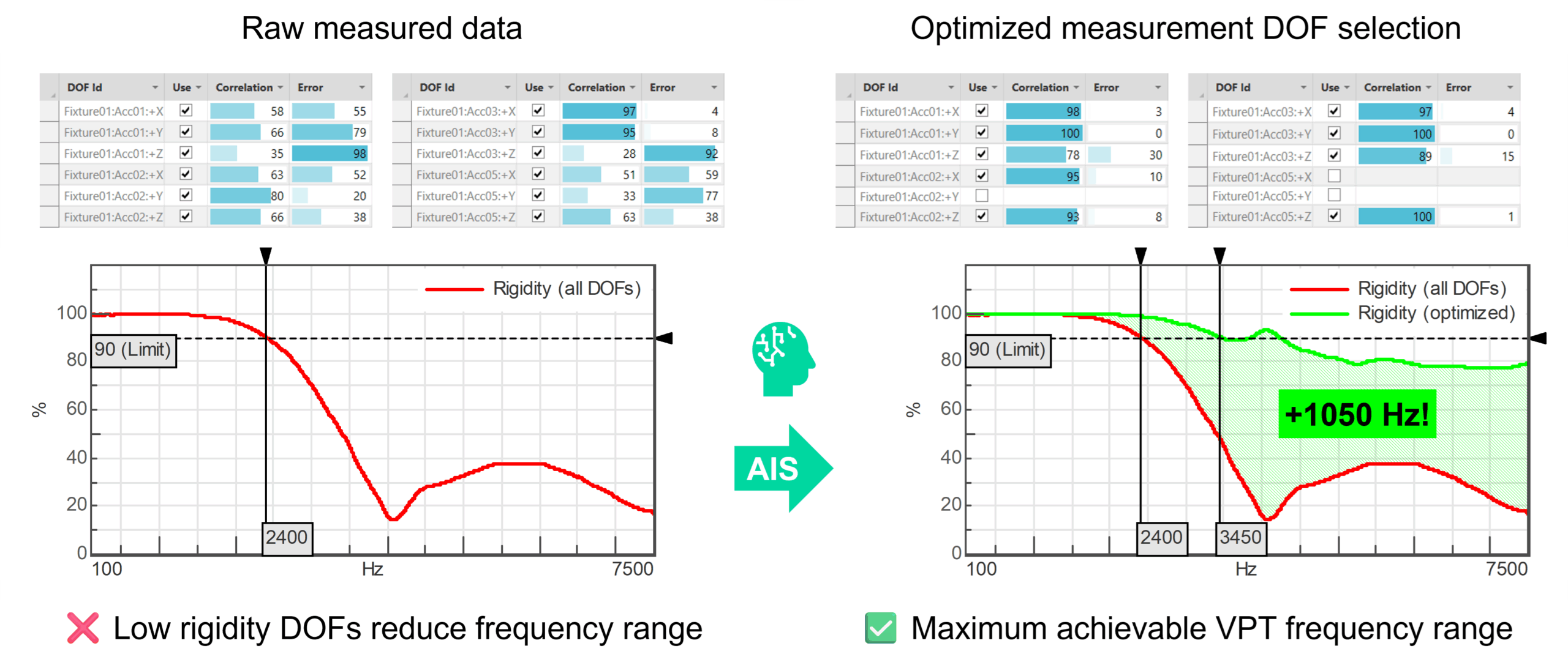
In our example, the rigidity metric already starts dropping off at a lower frequency than we had hoped (~2400 Hz). Does that mean we need to repeat the measurements to reach higher frequency ranges? Not necessarily! Simcenter Testlab’s Automatic Indicator Selection feature identifies measurement DOFs with low rigidity and automatically selects the best measurement DOFs which maximize the quality of the VPT results. This feature can greatly boost the frequency range of the transformation with no additional measurement effort.
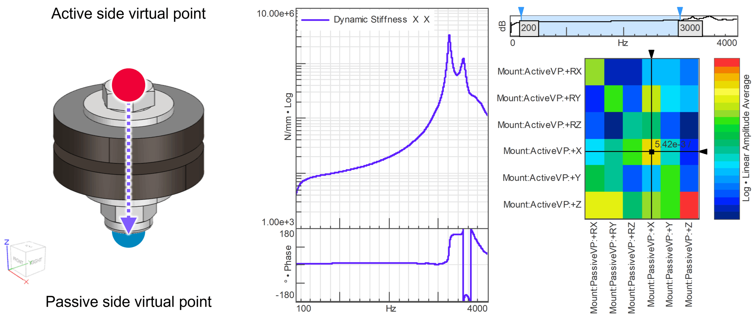
At the end of this 3-step workflow we are rewarded with our high fidelity mount model: a 6×6 dynamic stiffness matrix between all active and passive side coupling DOFs which is valid up to several kHz!
Conclusions
Simcenter Testlab provides a state-of-the-art workflow for estimating dynamic mount stiffnesses using Inverse Substructuring. The accuracy and frequency range of the results are maximized by automatically selecting the highest quality data for processing, making the end-to-end workflow extremely efficient and consistent across users.
Did you know Inverse Substructuring can also be applied under preload to capture dynamic stiffening effects such as torque projection? Read our article on controlling nonlinear dynamic mount stiffness in powertrain NVH prediction to find out more about how high fidelity mount models can be used effectively in the NVH development process.
Has this article left you curious to learn more about dynamic mount stiffness characterization? Watch our free webinar for an in-depth review of Inverse Substructuring theory and a software demonstration in Simcenter Testlab.