How to cool a spacecraft with heat pipes: co-simulate with Simcenter 3D Thermal and Simcenter Amesim

Heat Pipes are often used to cool electronic devices and spacecraft are no exception. The James Webb Telescope cost $10 Billion dollars and 30 years to develop. Like most endeavors in space, there was only one chance to succeed. However, the techniques and technology used for this telescope are unlike any other. With no way to test the complete system on the ground, simulation was the only viable way to ensure the project was a success.
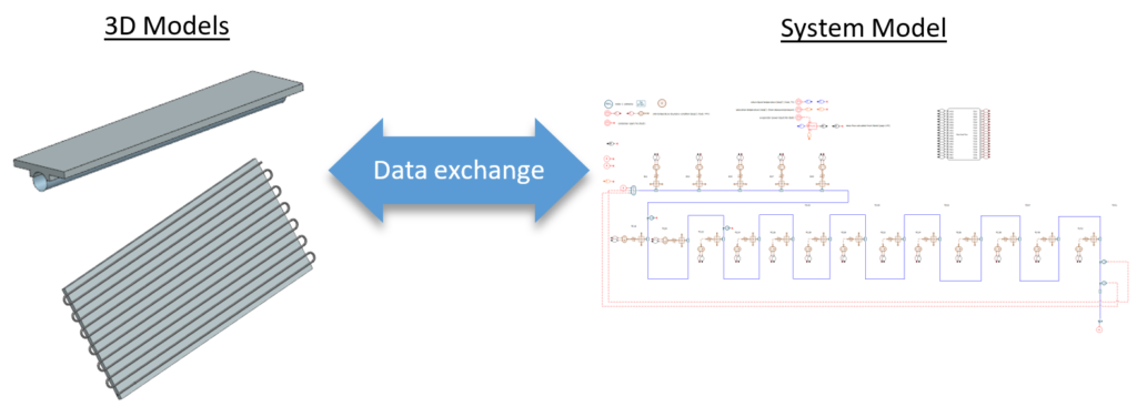
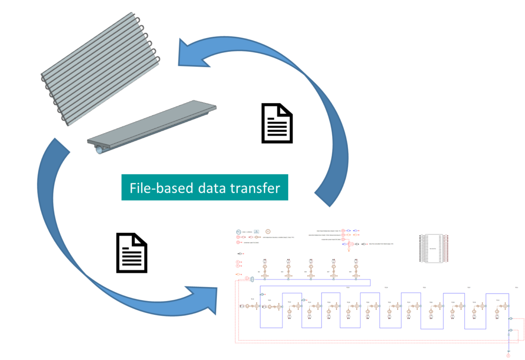
The Digital Twin is a combination of different representations of a product and can include everything from system-level models to full 3D models. Each of these models fulfills a specific need and answers a specific set of questions. During the design cycle, each team needs to communicate its results with other teams. Typically, the model-based systems engineers and 3D analysts work in a disjointed manner where data sharing occurs through file exchange. This approach to data sharing is frequently manual (i.e., via USB, email, etc.), which is difficult to scale, prone to error, and less conducive to seamless teamwork. In the increasingly interconnected systems developed today, it is more important for experts to collaborate more easily, particularly within multidisciplinary teams.
Improving Collaboration
Spacecraft are complicated machines, and managing their thermal characteristics is a complex endeavor. The challenge requires expertise from many different domains and employs several different strategies. For instance, the new James Webb Telescope needs to keep its instruments at very cold temperatures. A solar shield keeps them out of the sun’s line of sight. It is also necessary to account for the thermal characteristics of its other components. Heat pipes are a common device used to move thermal energy from one part of a system to another. They rely on the phase transition of the working fluid to transport thermal energy and boast a very high effective thermal conductivity.

The mechanically driven thermal control loop
To ensure the performance of the electronics, components need to be kept at a consent temperature. This is no small feat with parts of the craft having an operating temperature of 34.4 kelvins (minus 397.8 degrees F), although this is the mirror section it highlights the extreme conditions the telescope is working in.
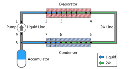
A common way engineers cool a device is with a thermal control device such as a mechanically driven fluid loop. This device consists of an evaporator that serves as a heat sink and draws excess thermal energy away from electronic equipment. A condenser rejects the excess heat to the environment, and an accumulator stores excess fluid and acts as a buffer that stabilizes the system’s operation.
Heat pipe model Set-up
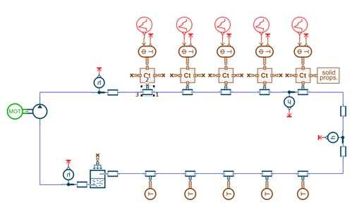
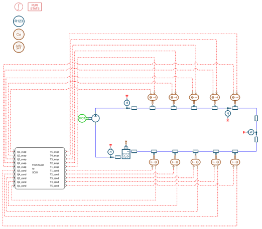
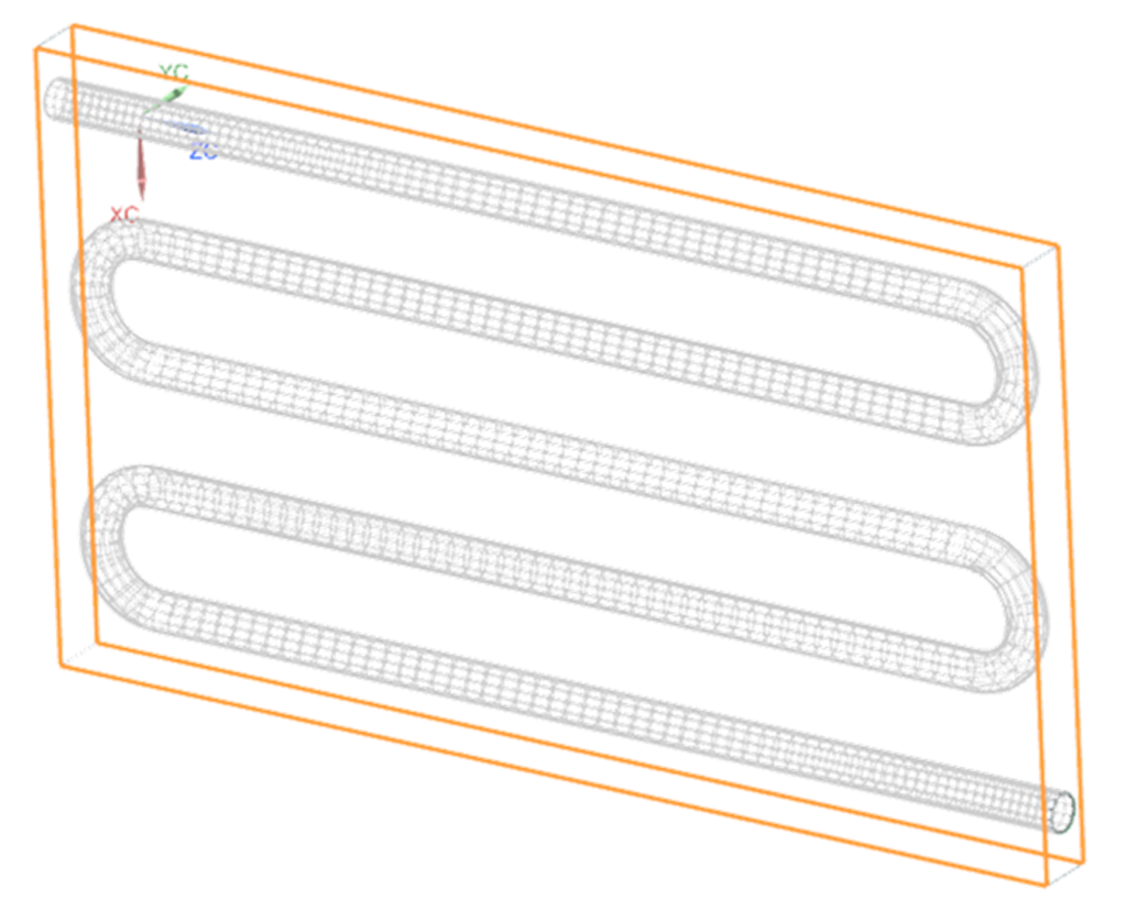
Usually, for such large projects, they are initiated by a systems engineer who creates a system model in a tool such as Simcenter Amesim. In this case, the model would represent the fluid loop. The evaporator and condenser pipes are discretized into five sections to represent each leg of the coils. This model will serve as the baseline to which we will compare the co-simulation results.
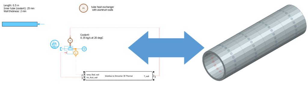
The intent now is to represent both the evaporator and the condenser in 3D. This is normally done in a 3D simulation tool such as Simcenter 3D Thermal Multiphysics. If both Simcenter Amesim and Simcenter 3D are used then the engineer can connect the condenser and evaporator models to the system model in Simcenter Amesim.
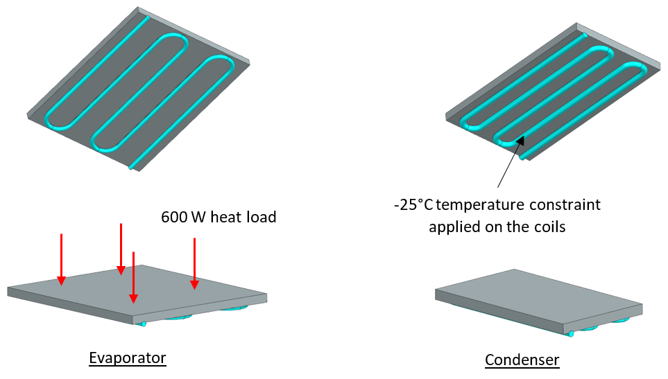
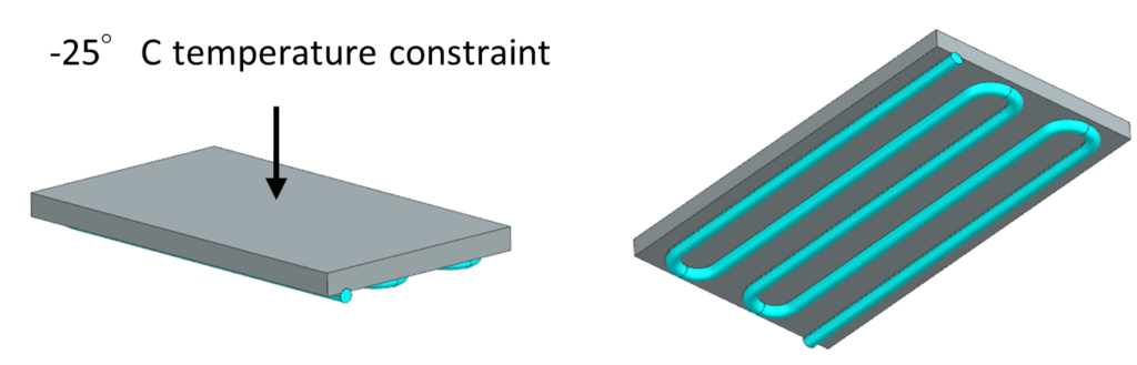
A temperature constraint is applied on the condenser coils and a heat load in Watts is applied on the base plate of the evaporator. The coils are divided into five sections, each of which will be connected to the discretized pipe components in the System model. Thermal Convective Zones are created for each section, so that data is useable in both the system and 3D models.
Sharing data between heat pipe models
If using older software packages then the engineer will need to find a way of sending heat fluxes to the 3D model and returning solid wall temperatures back to the system model. At Siemens, our developers have resolved this problem. An engineer can modify the original Simcenter Amesim model to include a co-simulation block. They can then send heat fluxes to Simcenter 3D and returning the solid wall temperatures. This allows them to generate the model DLL file and point to it in the Simcenter 3D using the External Conditions modeling object.
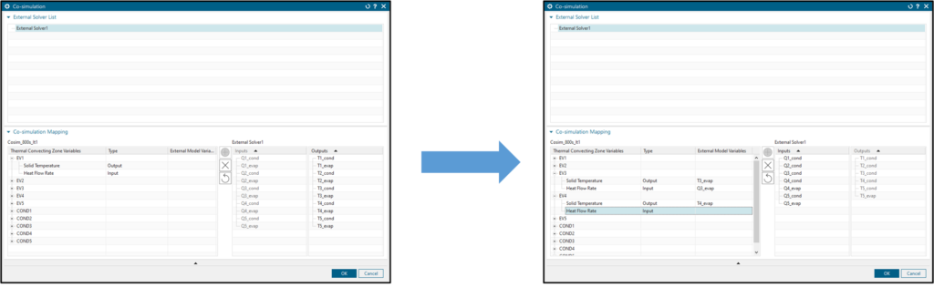
The Co-simulation UI reads the shared Simcenter 3D and Simcenter Amesim DLL file to present the available interfaces and data to be exchanged, which are then connected to their respective Thermal Convecting Zones. The model may now be solved.
Checking the set-up
The first thing to check is whether the two models are truly equivalent. An engineer will compare the heat flow rates on the evaporator and condenser in each model. A heat load of 600W had been applied on the evaporator, which is balanced by the heat rejection from the condenser. In the Simcenter Amesim model, this heat balance is maintained. In the co-simulation model, we see the same amount of heat rejection and similar dynamic behavior. Both models converge to steady operation.
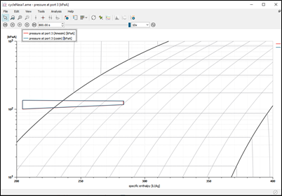
An engineer should also check the thermodynamic cycles of both models. Since both cycles overlap, they can be confident that both models represent the same physics.
Driving innovation
Now the engineer has established that they can replicate the physics in both a purely system model and a co-simulation model, they can start to explore the design itself.
The first step in the design process will be to change the temperature constraint of the condenser on the plate and not directly on the coils. Indeed, the top surface of the condenser plate faces the external environment and is subject to the temperature of the space environment. This will allow the thermal analysts to enhance the accuracy of their co-simulation model by considering all the 3D heat transfer effects of the condenser.
First Improvement
Now the engineer can investigate a new condenser design that consists of a fully immersed condenser. This configuration will provide more cooling performances since both sides of the condenser will reject heat to the external environment. This configuration is particularly interesting from a co-simulation point of view since the 3D heat transfer effects are driving the heat dissipation from the coils to the external environment.
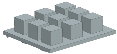
Finally, the heat loads from the equipment are uniformly dissipated on the evaporator plate while in real industrial cases, each piece of equipment dissipates heat individually. Thus, the engineer can leverage the co-simulation capabilities to investigate the effects of the heat load repartition on the evaporator performances.
Summary
It is clear that modeling heat pipes can be very complex due to the inherent two-phase nature of the heat transfer. The material properties and internal design specifications are difficult to determine. While systems-level models and correlations derived from experimental data can be used for modeling heat pipes, the true three-dimensional nature of the heat transfer is not captured. Conversely, modeling the process fully in 3D can be both cumbersome and time-consuming.
One option is to feed the system model with data from a set of 3D simulations. While this can help improve the accuracy of the system model, sharing the data through files still represents a disjointed process that requires multiple iterations to converge on a model that correctly represents the system and physics. Some teams try to develop a script or custom code that handles this data exchange automatically and satisfies the user’s requirements. However, this can be challenging to implicate code development, physics expertise, and numerical convergence knowledge. A further complication with one-off bespoke solutions is that they may not be easily extendable to interface with other solvers or codes.
The solution is to enable direct communication between the system and 3D models, thereby allowing seamless data transfer and leveraging the strengths of both solvers.
Co-simulation with Simcenter 3D Thermal Multiphysics and Simcenter Amesim
In Simcenter 3D Thermal Multiphysics 2206, it is now possible to perform direct co-simulation with Simcenter Amesim. The solvers exchange data directly during the simulation.
A new custom UI has also been added to simplify the model setup. You can assign the data interfaces in a visual and intuitive manner.
References
Sunada, Eric, et al. “A two-phase mechanically pumped fluid loop for thermal control of deep space science missions.” 46th International Conference of Environmental Systems, 2016. link


Comments
Comments are closed.
It looks to me as if the figure next to the headline “Sharing data between heat pipe models” could be wrong: the figure shows a SCADAS device, but the caption says “Simcenter Amesim model of the loop heat pipe that includes the co-simulation block”.
Hi @andreas.schwerin, I have been in contact with the Product manager regarding your question. He reassures me that the image caption is correct. It is simply a case that the schematic of a SCADA looks similar to a Simcenter Amesim model.