Inverters: the heart of electric vehicles
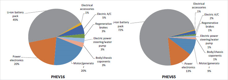
The electric vehicle inverter is an essential organ of the powertrain, yet it is often overlooked compared to batteries or electric machines. Looking at this study from NAS (2010), it is the most expensive component of a PHEV, second only to the battery.
Based on this, it must be carefully engineered. This is what is described in this post.
Simcenter Amesim and the analogy with the human heart
Why the heart? Because it drives the blood (i.e. energy or electricity) across the different organs (i.e. electric motor, battery, on-board charger, etc.).
And just like the heart chambers and ventricles pump blood throughout the body, the inverter’s transistors and diodes pump electrons in and out of electrical circuits. The blood pressure is equivalent to the voltage level and you will need to have a high enough pressure for the blood to be able to properly irrigate your brain.
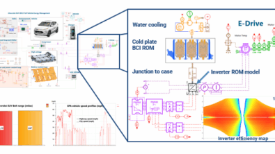
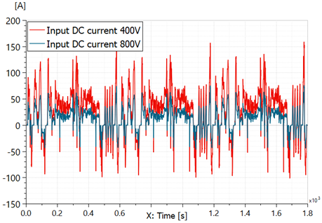
Simcenter Amesim, leading system simulation solution for electrification, allows you to compare different voltage levels of an electric vehicle and see the impact on current levels, current quality and powertrain efficiency.
Once the voltage level is defined, we can select the transistors’ technology, typically an IGBT or a MOSFET.
This can be done in two ways in Simcenter Amesim: either import data coming from a datasheet or import conduction and switching waveforms coming from Xpedition AMS or PartQuest Explore.

The comparison of different transistors and their impact on the electric vehicle range is deduced from the system simulations. Here for a midsize electric vehicle with a 68 kWh battery on SFTP-US06 driving cycle:

Inverter switching frequency importance
The electric vehicle inverter switching frequency is like the BPM (beats per minute) and, like a doctor with a stethoscope, Simcenter Amesim can assess the noise vibration and harshness behavior of an inverter using a spectral map:
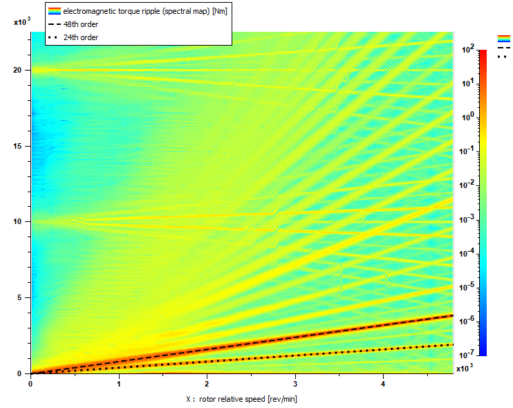
Here, the impact on the torque ripple of the electric machine is observed. The electric vehicle inverter switching frequency is 10 kHz and its first harmonic is observed at 20 kHz.
On the electric side, high frequency current fluctuations are called current ripple. To avoid ripple propagating through the DC bus, a DC link capacitor is needed. It will become the preferable path for high frequency AC.
The DC link capacitor is also used to stiffen the DC voltage i.e. reduce the ripple voltage.
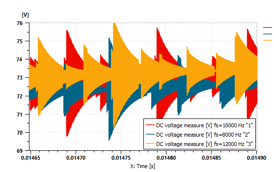
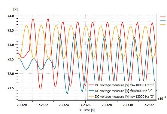
Increasing the switching frequencies require smaller DC link capacitors, leading to smaller components and to a higher power density for the inverter. Here is a comparison of voltage ripple for different switching frequencies, with a DC link capacitor of 0.005 F:
Electric vehicle inverter thermal management
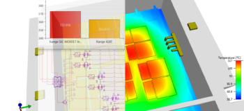
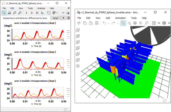
Increasing the switching frequency (the BPM), will lead to more heat released by the heart. Since the inverter is a complex piece of engineering, accurately capturing its transient thermal behavior requires either a 3D CFD or a testing approach. Indeed, some inverter locations like a transistor’s junction temperature can face hot spots. Temperature can go beyond specified limits and the semiconductor can fail or accumulate thermal fatigue.
To accurately identify these hot spots in Simcenter Amesim, two model reduction techniques are available:
- Cauer/Foster representation of individual transistors, import from Simcenter T3STER or from a datasheet
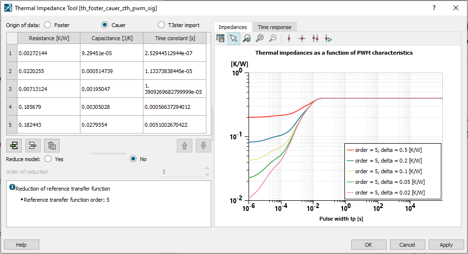
- Inverter boundary condition independent reduced order model FMU (BCI-ROM FMU) coming from Simcenter Flotherm
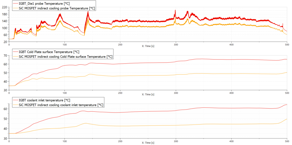
The curves below show IGBT’s and SiC MOSFET’s junction temperatures comparison over an SFTP-US06 driving cycle. The Silicon carbide high thermal conductivity leads to lower switching losses and lower temperature. This enables to lower the cooling system capacity and/or to increase the inverter’s switching frequency.
Inverter dysfunctional analysis
Now that the heart of electric vehicles has been described in normal operating conditions, let’s see what happens when it fails, for example in case of “fibrillation”.
Atrial fibrillation is an irregular and often rapid heart rate that can increase your risk of strokes, heart failure and other heart-related complications.
During atrial fibrillation, the heart’s two upper chambers (the atria) beat chaotically and irregularly — out of coordination with the two lower chambers (the ventricles) of the heart. Atrial fibrillation symptoms often include heart palpitations, shortness of breath and weakness.
An electric vehicle inverter could suffer from fibrillation when, for example, a current sensor is short-circuited to ground, or if the machine speed sensor suffers from an offset or returns erratic values. The following video depicts the thermal and electrical consequences of such failures.
To conclude, the inverter is a complex component, just as the heart is. It takes some engineering efforts to understand and master the proper operation of an electric vehicle’s inverter. These efforts are reduced by relying on advanced simulation methods like the ones present in the Simcenter portfolio.
If you want to know more about the complete inverter design process and see Simcenter Amesim in action, please register to this on-demand webinar.
See here how GKN reduced eDrive time-to-market and prototype loops for electric vehicles using this engineering workflow.
And if you were looking for actual heart simulations, we can also help you as demonstrated with this Simcenter STAR-CCM+ Fluid-Structure Interaction simulation of a trileaflet heart valve.