Fluid-structure interaction (FSI) of a Trileaflet Heart Valve
A long-awaited opportunity
Working from home has become the new normal for many of us. And while schools and day cares remain closed in some areas, parents continue to face the challenge of parallel work and childcare. I am one of those parents.
With the summer vacation period came the opportunity to focus only on work for two weeks. A long-awaited opportunity to challenge my skills on an old pet project of mine – the fluid-structure interaction (FSI) modeling of a trileaflet heart valve.
Will I be able to simulate a trileaflet valve in two weeks time with nothing else than my three years old desktop and Simcenter STAR-CCM+? Read this blog to find out!
What is a trileaflet heart valve and why care?
The Centers for Disease Control and Prevention (CDC) is a national public health institute in the US. According to the CDC, roughly 2.5% of the US population suffers from Valvular Heart Disease, a disease or damage to any of the four valves in the heart. It is being estimated that worldwide roughly 250 000 prosthetic heart valves are being implanted each year.
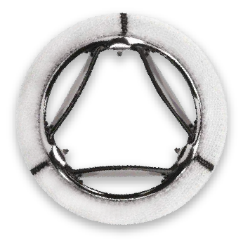
The first prosthetic heart valve was a ball valve, introduced by Hufnagel and implanted in 1952 (see Ref. 1). Essentially a valve based on the principal of rigid body motion. Trileaflet valves were introduced later. They open and close because of the deformation of flexible leaflets. You can read a full history of the evolution of heart valves here.
Modern rigid valves are made of plastic, carbon or metal. They are robust and last a lifetime. Unfortunately, the blood tends to stick to the valve, and the patient will have to take blood thinning medicine.
Trieleaflet tissue valves on the other hand feature leaflets made of tissue. The tissue is taken from a human or animal donor. Such valves mitigate the need for blood thinning, but they are less durable.
Alternatively, the tissue can be replaced with advanced polymers. Such trileaflet polymer valves have the potential to combine durability with hemocompatibility (see Ref. 1). In other words, they could last a lifetime and the patient would not have to take blood thinning medicine.
Why simulate with fluid-structure interaction (FSI)?
From an engineering perspective, it is of key importance to know how much fluid will flow through a valve for a given operating pressure. In other words, what is the mass flow rate for a given pressure upstream and downstream of the valve? Such performance data can only be obtained through experiments or simulation.
The key advantage of simulation is the fact that you don’t need access to a laboratory, nor do you need a prototype of your valve. All you need is a computer, and a Computer Aided Engineering (CAE) software capable of accurate fluid-structure interaction (FSI) modeling. You will have to extract the fluid domain, discretize it, and solve the governing equations of fluid flow on the discretized representation.
But what does it take to extract the fluid domain? First, you need the open configuration of your valve. For a rigid valve, you can simply rotate or translate a geometric part to open or close the valve.
To obtain the open configuration of a trileaflet valve is not that simple. You must compute the deformation of the flexible leaflets first.
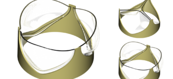
The animation below is from my most recent simulation of a trileaflet polymer valve using Simcenter STAR-CCM+. Simcenter STAR-CCM+ is ideal for the simulation of valves because it enables you to solve the governing equations of fluid flow and solid mechanics in one single integrated environment, enabling seamless fluid-structure interaction (FSI) modeling.
My previous attempts at modeling a heart valve
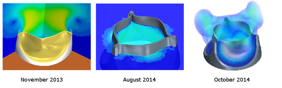
I find trileaflet valves fascinating, to say the least. Browsing through my work archive, I can see that my first attempt to simulate such a valve dates to November 2013. I repeated the simulation with improved post processing in August 2014 and October 2014.
The setup is a one way coupled simulation. Abaqus computes the displacements based on a pre-defined pressure load on the leaflet. A rigid obstacle is placed in between the leaflets to prevent complete closure of the flow path. The displacement is sent to Simcenter STAR-CCM+, where it is used to morph the fluid leaflet wall boundary. The fluid volume mesh is being rebuild periodically to cope with the large mesh deformation.
Could I do better today?
My simulations performed in 2013 and 2014 have many flaws. Most severe is the 1-way coupled setup, followed by the artificially enforced gap between the leaflets and the periodic remeshing of the fluid domain. Nevertheless, I still think it is best to approach such a complex simulation in stages, and to increase complexity step by step.
Seven years have passed since 2013. That equals roughly 21 Simcenter STAR-CCM+ releases! Time for an attempt at fluid-structure interaction (FSI) simulation of a trileaflet heart valve in two weeks time with nothing else than my three years old desktop and Simcenter STAR-CCM+.
I will assume symmetry and model only a 60°- degree sector. I will enforce a small gap between the leaflets but this time, I will use an overset mesh setup instead of periodic remeshing. Finally, I will compute the displacement of the leaflet for one cycle upfront, store it in a file, and import the displacement on demand to prescribe the leaflet motion in the fluid model.
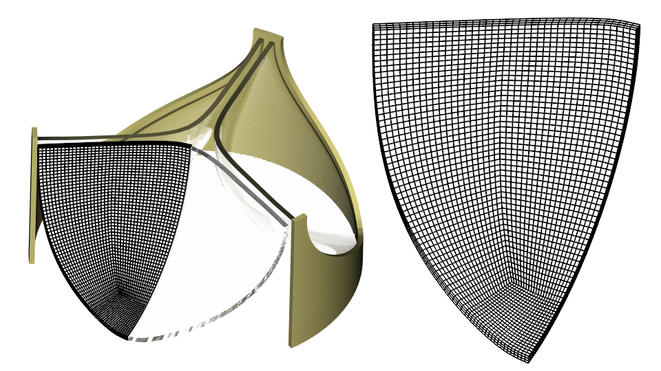
Geometry and Finite Element mesh
I use the 3D CAD Modeler in Simcenter STAR-CCM+ to build the geometry as described in Ref. 2. My frame has a diameter of 24 mm and my leaflets are 0.4 mm thick. I build a mesh with three Hex 8 elements over the leaflet thickness using a Directed Mesh Operation.
Material properties, loads and constraints
I will use the material properties reported in Ref. 2. Looking at the numbers, I realize that the reported Young’s modulus is 3.2 MPa, and the Poisons ratio is 0.49. For a comparison, the Young’s modulus of steel is roughly 65 thousand times higher! Such a low Young’s modulus together with a leaflet thickness of 0.4mm makes for a very flimsy structure. On top of that, the Poison’s ratio of 0.49 indicates that the material is nearly incompressible, making it an even harder problem to solve.
At least the constraints are straight forward, symmetry and a fixed constraint. I will apply the periodic pressure reported in Ref. 3 on the outer leaflet surface to open and close the valve. The period of one pressure cycle is 0.861 seconds.
Enforcing a gap between the leaflets
A contact constraint will enforce a gap between the leaflets throughout one pressure cycle. Specifically, I will define a frictionless contact between the inner leaflet surface and a rigid plane. The image below shows the distance between the inner leaflet surface and the rigid plane for the initial configuration.
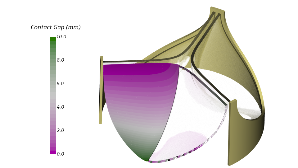
Frictionless contact with a rigid plane obstacle has been released with Simcenter STAR-CCM+ 2020.2. The implementation is based on a penalty formulation, and the penalty parameter specifies the contact stiffness. Low values may allow for penetration, very high values may slow down the convergence. I will set the penalty parameter to 1.0E14 Pa/m. This rather high value will prevent the leaflet from penetrating the rigid plane.
The snap through instability in heart valves
A trileaflet valve has a significant stiffness around the closed and the open configuration. For any configuration in between the stiffness is nearly zero. This is called a snap through instability.
To resolve the snap through instability is important in hindsight of the fluid-structure coupling. A significant amount of fluid needs to be accelerated by the leaflets during the snap through. At the same time, the leaflets will have almost no stiffness. This make for a strong coupling between fluid and solid.
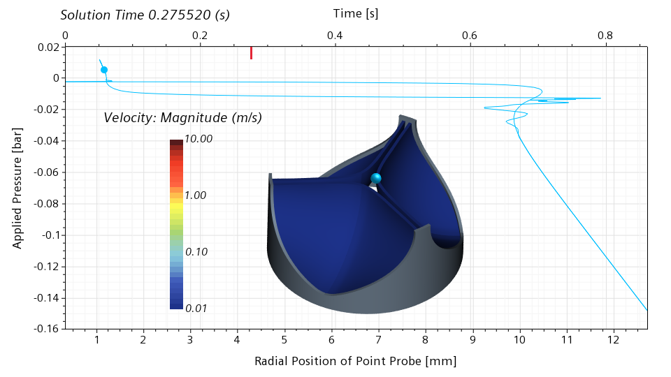
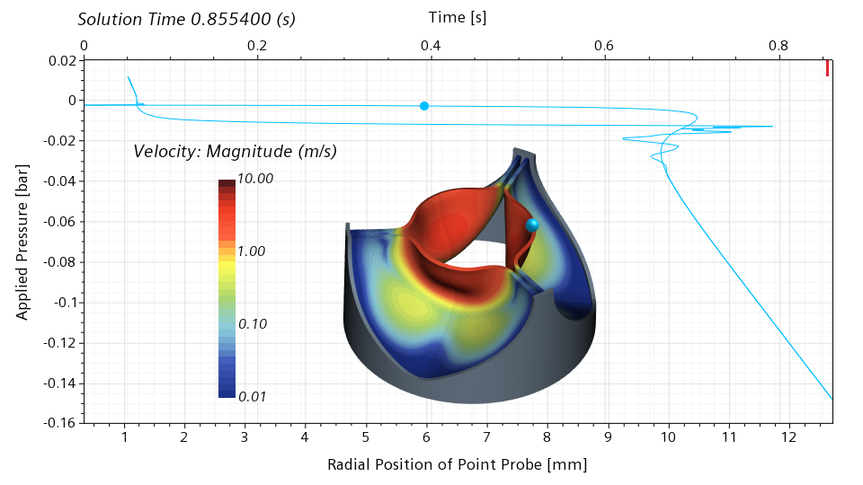
I will use my simulation results to illustrate the snap through in more detail. In the scene below, I show the velocity magnitude on the leaflet surface. In addition, I show a point probe on the leaflet edge. This point probe follows the motion of the leaflet. In the graph, I show the applied pressure on the vertical axis, and the radial position of the point probe on the bottom horizontal axis. The red bar on the top horizontal axis shows the physical simulation time.
Below is a snapshot corresponding to 0.275520 seconds, roughly 32% of the cycle. The valve is still nearly closed. The blue dot in the graph indicates the current pressure and the current radial position of the point probe. The slope of the graph in the vicinity of the blue dot is high. This means that a significant change in the pressure is required for a significant change of the radial displacement. With other words, the valve has a significant stiffness around the closed configuration.
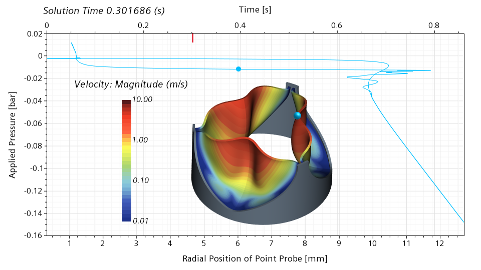
Moving forward to 0.301686 seconds, roughly 35% of the cycle, we can see that the valve is now half open. The slope of the graph in the vicinity of the blue dot is close to zero, meaning that the valve has literally no stiffness around the half-open configuration. Even the slightest change in the pressure will lead to a dramatic change of the radial displacement.
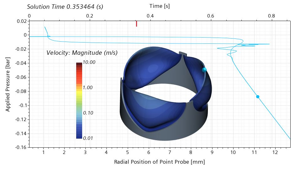
The valve recovers the stiffness around the open configuration, and loses it again around the half-closed configuration. Comparing the half-open and half-closed configuration, it is interesting to notice that the valve doesn’t open and close in the same way.
Below is an animated version of the scene. The frames are not equally spaced in time to better capture the opening and closing event.
A dynamic step size control
For a 2-way coupled fluid-structure interaction (FSI) of a heart valve simulation, it is critical that the change of the displacement between two consecutive time steps stays within limits, also during the snap through. Otherwise, too much fluid needs to be accelerated in a single step, and it becomes challenging to keep the solution of the coupled fluid-structure system stable.
The change of the displacement between two steps can be controlled through the step size. Ideally, a large step will be used whenever possible, and a small step will be used whenever necessary. In Simcenter STAR-CCM+, it is straight forward to achieve this with a dynamic time step control.
I use a field history, a user defined field function and a maximum report to monitor the change of the displacement between two steps. In case the change exceeds an upper limit, I cut the step size in half, in case the change drops below a lower limit I double the step size. It takes just a few lines of Java to script this basic, yet powerful control.
In the animation below, I plot the von Mises stress on the leaflet surface. In addition, I show a graph of the applied pressure over time. Thanks to the controller, the time step is large before and after the snap through event. During the snap through, the time step is very small time. This is ideal and makes the fluid-structure interaction (FSI) of heart valve simulation computationally very efficient.
Did I accomplish what I challenged myself to do?
I did challenge myself to carry out a 1-way coupled simulation of a trileaflet polymer heart valve using only Simcenter STAR-CCM+ and my three years old desktop in two weeks’ time. Did I accomplish that?
Yes! But so far, I have only managed to describe a few highlights of the fluid-structure interaction (FSI) model. To cover the remaining material in one big blog is not possible.
Let me close with a sneak preview of my fluid mesh deformation strategy – a combination of morphing and overset meshes. The animation shows a subset of my meshes. The cells in yellow are inactive, cells in blue are active, while cells in red are acceptor cells. Grey cells are acceptors used as donors, but no such cells exist in the model. In green you can see parts of one leaflet.
I hope you will agree with me that this mesh evolution strategy is powerful, especially for fluid-structure interaction (FSI) of heart valve simulations. But even more, I hope that you are looking forward to another blog revealing the secrets behind this dynamic mesh evolution.
Outlook for fluid-structure interaction (FSI) of heart valve
Having built and tested the fluid-structure interaction (FSI) model together with the fluid mesh deformation strategy, it is now time to attempt a 2-way coupled fluid-structure interaction (FSI) simulation. Such a simulation will provide detailed engineering insight into the operational performance of a trileaflet polymer heart valve.
But trileaflet heart valves have been simulated before, so what is new? With Simcenter STAR-CCM+, it will be possible to automate the simulation and to parameterize the CAD model. As a result, you will be able to analyze many designs, not just one. This will significantly speed up the heart valve design process and will make it possible to find better heart valve designs faster.
References:
Ref 1. Claiborne TE, Slepian MJ, Hossainy S, Bluestein D. Polymeric trileaflet prosthetic heart valves: evolution and path to clinical reality. Expert Rev Med Devices. 2012;9(6):577-594. doi:10.1586/erd.12.51 (https://pubmed.ncbi.nlm.nih.gov/23249154/)
Ref. 2: Kouhi, Esfandyar & Morsi, Yosry (Yos). (2013). A parametric study on mathematical formulation and geometrical construction of a stentless aortic heart valve. Journal of artificial organs : the official journal of the Japanese Society for Artificial Organs. 16. 10.1007/s10047-013-0719-z.
Ref. 3: Giulia Luraghi, Wei Wu, Francesco De Gaetano, Josè Felix Rodriguez Matas, Geoff D. Moggridge, Marta Serrani, Joanna Stasiak, Maria Laura Costantino, Francesco Migliavacca. Evaluation of an aortic valve prosthesis: Fluid-structure interaction or structural simulation?. Journal of Biomechanics, Volume 58, 2017, Pages 45-51. ISSN 0021-9290. https://doi.org/10.1016/j.jbiomech.2017.04.004. (http://www.sciencedirect.com/science/article/pii/S0021929017302026)


Comments
Comments are closed.
Rafael
Very beautiful work. I’m happy to see that the STAR-CCM+ team has continued to improve capabilities to make such difficult and important engineering problems possible
Alan