Simcenter STAR-CCM+: 4 Keys to Handling Complex Geometry in your CFD Simulation
“Simplicity is the ultimate sophistication” – Leonardo da Vinci
What does this mean for people tackling the ever-growing system complexity required to meet the demands of tomorrow? Counterintuitively, in almost any domain, complexity must be mastered through simplicity: complex problems need to be broken down into a set of elegant, robust principles and parts. It’s the same for CFD geometry preparation with thousands of complex parts: simplifying the workflow is key.
Kawasaki Motors provides one example of how to work on a complex assembly that was improved with a streamlined CFD workflow. To address the problem of reducing design turnaround time, the team working on the Kawasaki Ninja H2R/H2 turned to Simcenter STAR-CCM+ for their solution: with tools like filters, automated mesh pipeline, and the surface wrapper, they were able to cut down their CAD-to-Solution time by 75% and achieve 40% improvement in radiator ventilation flow for cooling the engine and lower front-wheel lift. Most notably, they reduced overall manual CAD cleanup time by 85% with surface wrapping tools– a tool that simplified the entire workflow.
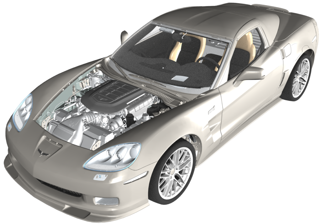
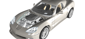
In CFD modeling, there are three key ways in which Simcenter STAR-CCM+ can help you handle complex geometries in your simulation. Let us look at one of the most complex systems and CFD simulations in the world – Vehicle Thermal Management (VTM) for a full passenger car, in this case the formidable Corvette.
Easily Organize Complex Models for Simulation
The Corvette model shown below has more than 15,000 parts, not all of which are needed for the simulation. Manually searching for and organizing the parts can involve thousands of clicks, miles of mouse travel, and several units of your favorite caffeinated beverage to get the job done.
Fortunately, several capabilities exist to simplify the job, including tags, filters, and query-based selections in Simcenter STAR-CCM+. These allow you to more efficiently organize large complex assemblies and ultimately automate the mesh pipeline.
To organize the Corvette model, you can:
- Tag the parts to create a new grouping without altering the original imported hierarchy (so don’t be afraid to try it out). Groupings can be made based on qualities like ‘material’ or solid part or exterior parts of the car: for example, all the plastic parts in the powertrain can be grouped and combined as a single part. This allows you to organize and reduce the number of parts used as input to fluid regions.
- Use the tags as an input in filters or the query-based selection in the mesh operation pipeline. Using the filter to create a query-based selection makes it possible to find and select objects in the simulation tree without having to do it manually, producing more accurate results in a fraction of the time.
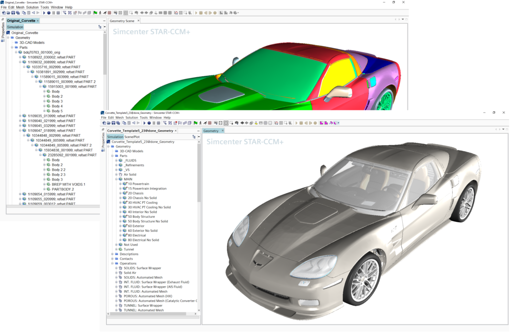
After organizing the model using tags and groups, the model’s original count of 15,000 parts has been reduced to around 8,000 for the VTM simulation. The image below shows the re-organized hierarchy tree for parts.
Reduce Turnaround Time from Weeks to Hours
Last year during a Simcenter Conference training session called “Meshing made Easy,” attended by simulation engineers from around the world, the trainer asked the question, “Have you ever seen perfect geometry?” Not a single attendant raised their hand – no one in the room was confident enough to say that they had ever gotten perfect geometry that was simulation-ready. Seeing perfect geometry is equivalent to seeing a flying unicorn!
In a model with a few parts, CAD preparation involves cleaning up the dirty geometry, unite the parts, and extract the fluid volume manually without any problem. The same workflow, however, cannot be used to handle a full vehicle or a ship model; a manual geometry preparation of model with thousands of parts equates to weeks or months of tedious work, putting serious speed limits on product development. You need to go from CAD-to-Solution rapidly in order to study and produce the best designs.
One way to achieve this is with the Simcenter STAR-CCM+ Surface Wrapper tool, which creates a geometric representation of the model by “shrink-wrapping” a high-resolution triangulated surface on the complex aspects of the geometry. If doing a VTM analysis on our Corvette model, the entire car along with the ambient air surrounding the car can be easily generated with our surface wrapper technology in just a few clicks. The goal of using the surface wrapper is to prevent leakage into the main cabin, avoid geometry issues (missing faces, gaps, intersecting parts), capture the original geometry features, and make sure there is no artificial intersection between parts. Contact prevention, Gap closure, and Surface Wrapper Defeature options provide more controls to capture enough data from geometry.
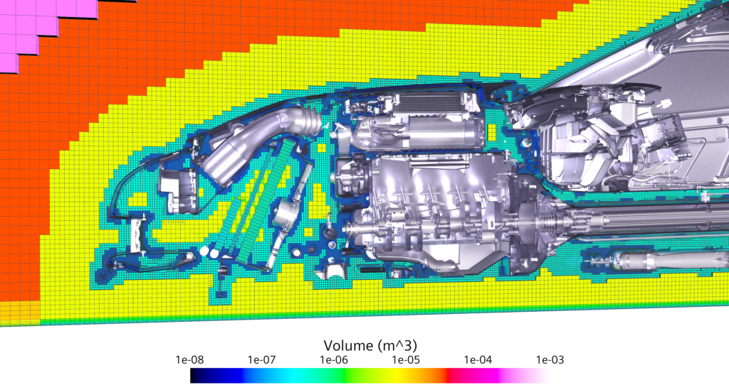
Fast, Robust, Pipelined Mesh Operations
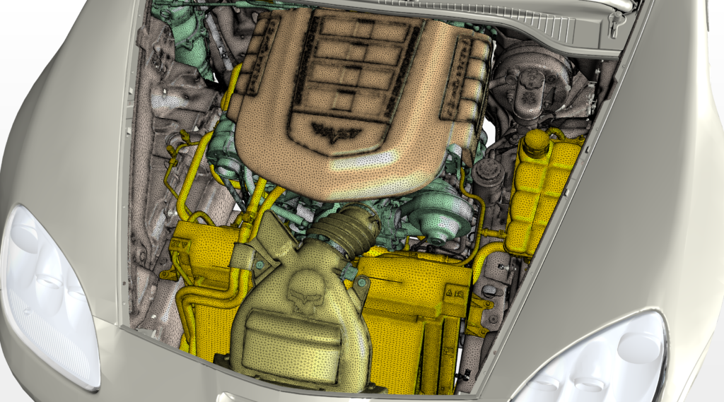
Next, you need to create a volume mesh for simulation. The mesh operation pipeline allows you to create a custom workflow that suits the needs of an application. With pipelined operations, the user can automate the execution, keep track of the operation sequence, and revert them in a fully reversible approach. After surface wrapping the Corvette model, you can add the automated mesh and weak contact creator in the mesh pipeline to create the final volume meshing for the VTM simulation (see image below).
Integrated CAD Environment
Next, changes to the design often need to be made. In our example, if the Corvette model needs to be investigated for the overall aerodynamic drag reduction impact on front end cooling then the grill, bumper vents, and radiator fan parts need to be parameterized. This can be easily done through our very own built-in 3D-CAD platform which allows you to create and parameterize CAD models without having to use external tools or depend on a design engineer to parameterize parts of a design study.
The search tool within the 3D-CAD platform allows you to find similar bodies or topologies and detect & visualize clashes or gaps between bodies which are not easy to find manually. Refer to my previous blog “Simcenter STAR-CCM+ 2019.3: Hidden in Plain Sight? Not Anymore – 3D-CAD Search Tool” to learn more about the search tool in 3D-CAD.
With the surface wrapper, automated mesh pipeline, your interactions within the CAD-to-mesh workflow are reduced and the overall effort required for handling large complex geometry is greatly simplified. What results is a smoother design process, deeper analyses, more polished designs, and engineers happier to go to work.
The meshing pipeline truly helps you do more with less and can dramatically speed up and improve the design process without any hidden costs.
Using these Keys to Unlock the Power of Simulation
Simcenter STAR-CCM+ is built from the ground up with a workflow that is as simple as possible to help you efficiently model the complexities of today’s engineering problems. This means that you will spend less time cleaning up and troubleshooting models and spending more time making design decisions to drive innovation. I invite you to go ahead and download the latest version of Simcenter STAR-CCM+ to experience for yourself how “simplicity is the ultimate sophistication.”
See also:
5 tips to unleash that one-off CFD simulation
Stitch in time with Simcenter STAR-CCM+ Surface Repair
Simcenter STAR-CCM+ 2019.2: if you love coding, don’t read


