Dread building a FE beam model? Create it in a snap with Simcenter 3D
The trouble with beam models
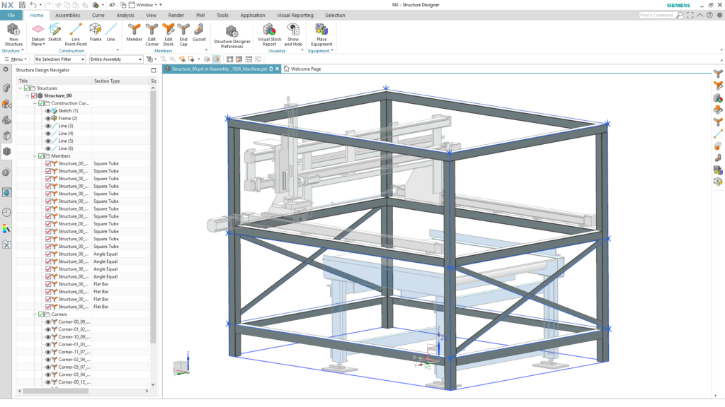
Welded frames are the backbone of an assembly, providing global stiffness to a whole assembly. NX recently introduced a new application, called Structure Designer, that is dedicated to modelling frame structures in CAD in a lightning fast way. Structure Designer tackles and eliminates challenges by automating tasks that used to require time and intensive manual effort, adding a rich library based on industry standards, and supporting structure reuse. It’s even faster to make changes to the design and automatically update the whole rule-based assembly.
These slender frames obviously need assessment for structural integrity. In finite element (FE) analysis, beam models are used to represent welded frames and are typically modeled as 1D elements. Historically however, creating 1D beam models that correctly match the CAD geometry has been a time consuming and tedious task that engineers dread. Creating beam elements properly in a FE preprocessor requires defining the centerlines and cross-sections for each beam. And that’s just for the first model. What happens when the design changes? Depending on the change, you might need to completely redo your FE beam model.
Wouldn’t it be great if there was a better way to automate the FE beam modeling creation process?
Automate beam modeling with Simcenter 3D
New capabilities in the upcoming releases of NX and Simcenter 3D will now give you the advantage of automating the beam modeling process. This will save you loads of time and let you go faster with simulating and analyzing your designs. Since models in Simcenter 3D is associated to the design, you can also rapidly update your FE beam models to any design changes made in NX.
Getting the wireframe geometry
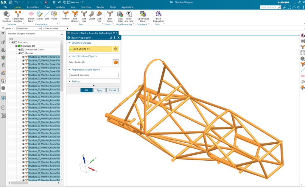
The process starts with building the corresponding wireframe geometry. Extracting centerlines, connecting them at corners, extending or splitting those centerlines, and extracting the cross-section geometry for each curve – these are all tedious, manual tasks that you don’t need to perform anymore.
Starting with NX 1980 series, NX Structure Designer provides a command named Beam Preparation. This command automatically selects all the members of the structure and generates fully defined idealized geometry in one go, regardless of the complexity of the structure!
Creating the FE model in one shot
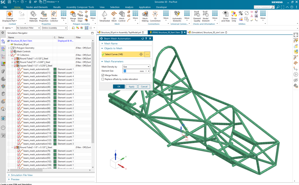
With the idealized geometry now in place, the only step that remains now is to create an FE beam model. To that end, the Simcenter 3D 2021.2 release introduces a new meshing command, Beam Mesh Automation. This command will automatically define cross-section and material properties for the curves based on data in the CAD model. You then just need to specify either the number of elements or the targeted element size and mesh all those curves. This lets you create the FE beam model in just seconds!
The magic here is that Simcenter 3D does not only generate the mesh, but it also automatically creates all required properties, such as cross-section and material definitions, which it also assigns to their respective meshes. You get a complete FE beam model all in one shot! There’s no need for you to check back and forth for consistency with the 3D CAD model. The process is completely automated!
No compromise on geometrical accuracy
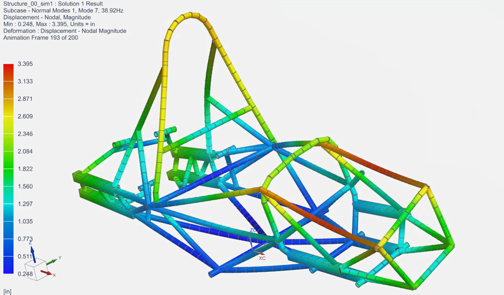
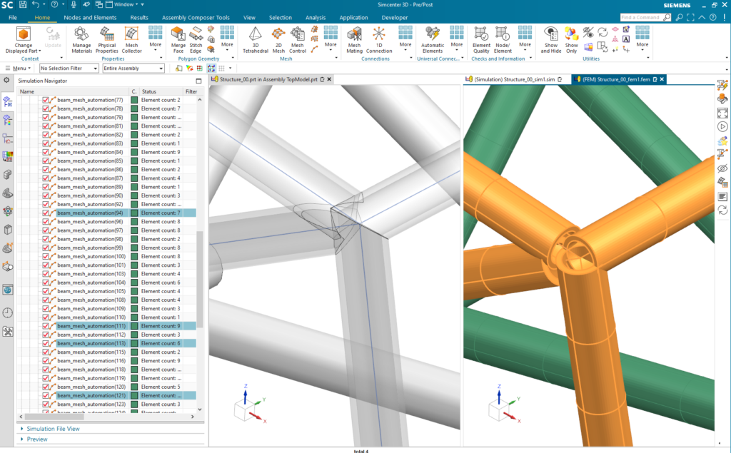
The physical nature of the CAD assembly implies that members do not overlap geometrically. However engineers often neglect to create the necessary offsets with respect to the geometrical point of connection due to the need to balance accuracy vs. the time required to accurately build the FE model. The Beam Preparation command in NX Structure Designer is very rigorous about maintaining those offsets in the three translational directions. In turn, the “Beam Mesh Automation” command will automatically take that offset data to align the FE beam model with its CAD counterpart. All that remains is to define and run a structural analysis, areas you normally would in Simcenter 3D!
Create the first beam model fast, update even faster!
Compared with the manual creation process, the new automated process with Simcenter 3D and NX already reduces modeling time by about 90%. After evaluating your design, you most likely will want to try some new designs. Simcenter 3D lets you explore far more design alternatives than you could have accomplished by using a manual process. Now updates of the design in NX Structure Designer will automatically trigger an update of the FE model in Simcenter 3D. You can update any dimension cross-section, or material property effortlessly. This means you can perform many more design-analysis iterations to find the right design that meets or exceeds requirements.
If you’re designing welded frame structures, the new NX release combined with the new Simcenter 3D 2021.2 release will completely streamline your process from design to simulation, and it will help you save time from modeling so you can spend more time engineering innovation!