See your simulation models in context with multiple tabbed windows
How do design changes impact your simulation model?
Simulation is really part of a broader design process. The intent of simulation is to prove that a particular design will meet performance requirements, and if the design doesn’t meet requirements, simulation will show where and why. Then analysts can even propose changes to the design that will make the design more robust to meet or exceed performance requirements.
However, simulation tools often don’t put simulation into the context of this complete development cycle. With other simulation tools, it can be difficult to see what kind of ripple effects a design change might have on your simulation model.
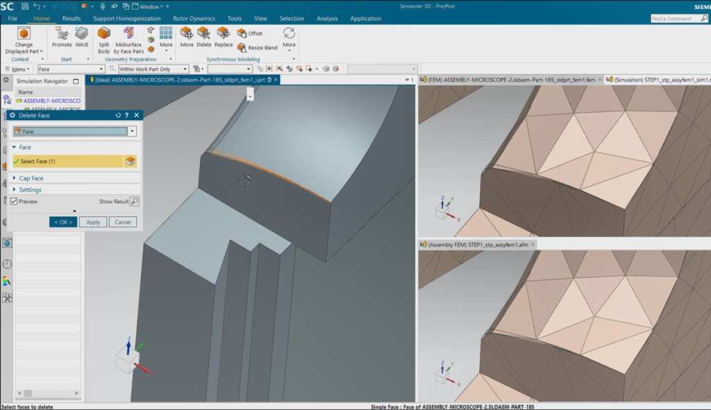
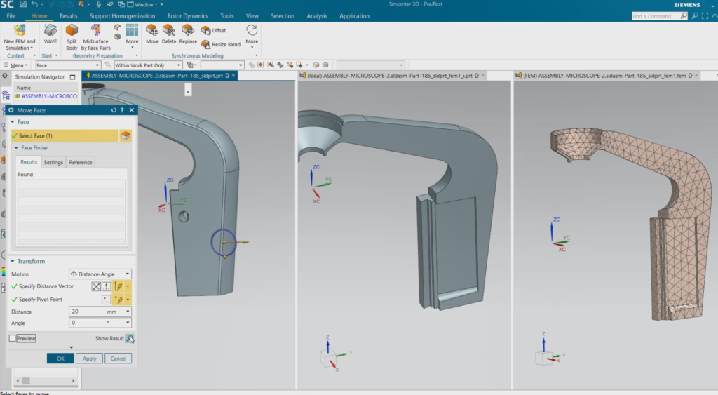
Put simulation modeling in context with multiple tabbed windows
A key strength of Simcenter 3D is the ability to put simulation within the context of the broader design development process. The Simcenter 3D Engineering Desktop, which is the simulation modeling environment for all Simcenter 3D solutions, excels in handling CAD geometry and supporting associative workflows from design through analysis. Since the simulation model is associated to geometry in Simcenter 3D, you can quickly make changes to geometry and see how that will impact your finite element analysis (FE) mesh, assembly and ultimately your simulation results.
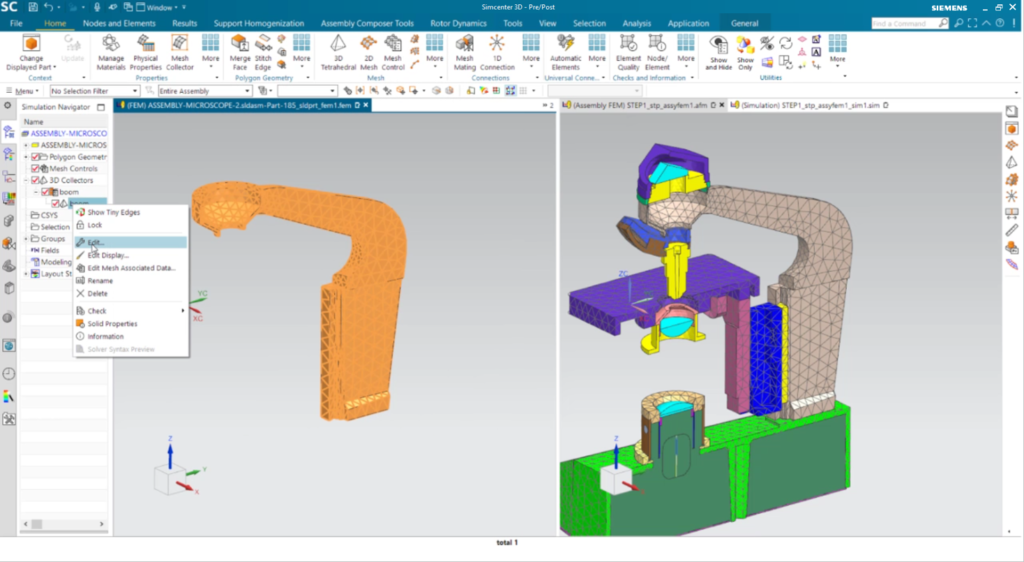
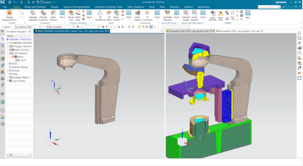
In our upcoming 2021.2 release, we have made the geometry and associative capabilities of Simcenter 3D even stronger with the addition of multiple tabbed windows. What this means is that you can have both your CAD part and FE model displayed simultaneously in separate windows on your screen. This helps you easily see how changes to your CAD part are realized in your FE model. You can even synchronize the part windows so that as you move and rotate your CAD part, the FE model view orientation in another window tracks with the CAD part. As you make modeling changes in the CAD part, you can easily update and view the FE model reaction to the CAD model changes. This shortens the design through analysis process and makes the whole experience much more seamless.
Efficient assembly modeling
Another key strength of Simcenter 3D is in its approach to assembly modeling. The Simcenter 3D approach mimics how CAD systems build and manage design assemblies by leveraging component parts, and then instancing and connecting those parts together into a complete assembly. Similarly in Simcenter 3D, you can create a single component FE model which you can then use to create multiple, “instanced” copies in an assembly FE model. This helps to streamline your overall simulation modeling process rather than having to manage a large, monolithic FE model like in other tools. If you make a design change to a component that’s used in an assembly, you can rapidly update your component mesh through the design-simulation model associativity outlined earlier. Then you can immediately apply the new component mesh to all of the instances within the full FE assembly mesh automatically.
This assembly modeling approach allows CAE teams to partition their work more easily, such that analysts can develop and analyze components and/or sub-assemblies independently before being brought together in a higher-level assembly. Customers of Simcenter 3D welcome this unique approach to assembly modeling. One customer proclaimed the assembly modeling approach in Simcenter 3D is “worth the price of admission.”
Quickly see how updates impact the assembly model
The new multiple tabbed windows capability makes the Simcenter 3D FE assembly modeling approach stronger. With multiple tabbed windows, you can view an assembly FE model in one window while viewing one or more component FEMs and/or sub-assemblies in other windows simultaneously. Similarly, you can synchronize the window viewing orientation across windows, such that changing the view in the assembly FE model will also track in the component FE model window, and vice versa. Any model changes made to a component FEM or sub-assembly in one window will immediately update and display in the related assembly FE model window. This makes it much easier for you to see how changes in the component model will affect the assembly, shortening the cycle between component updates and assembly modeling.
In summary
The new multiple tabbed windows capability in Simcenter 3D 2021.2 will help you see simulation in a broader context. You can now see instantaneously how design changes will ripple through your simulation component and assembly models. This will help you be more productive during the modeling and iteration process so you can go faster and get results sooner.