Antenna arrays and how to improve your signal.
Antenna arrays, you can find these everywhere from space missions to cell phones. Subsequently, antenna arrays are commonly located in congested airspace, where thousands of devices all communicate at the same time. In such environments, each antenna is producing noise that interferes with the signal of others. An engineer can design an antenna to improve the chance that an antenna can receive a signal.
How can engineers ensure they receive the signal?
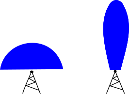
Engineers can increase the communication performance between transmitting and receiving wireless devices and base stations with beamforming. Without beamforming, the base station will spread the signal and its energy out omnidirectionally. With beamforming, it is possible to focus the EM energy into a beam. The engineer can then direct the beam towards a receiver, as shown in figure 1. By concentrating the signal and directing it towards the receiver, more of the signal, and comparatively less noise is received. The difference between the amount of the signal and the noise received is the Signal to Noise Ratio (SNR). Additionally, this technique benefits the surrounding receivers that are less likely to receive interference. Due to the concentrated beam having less spread and the ability to direct it away from other receivers. Beamforming is the core technology component that will enable high performant 5G and 6G communication of the future.
Beamforming and how to do it
To produce electromagnetic (EM) beams an engineer will use dedicated antennas and electronics. In the case of the antenna, its purpose is to convert the electric signal into an electromagnetic wave that propagates through free space. Every antenna has its own set of specifications that an engineer can fine-tune to the signal that they want to produce. In some cases, it is the shape of the antenna that enables it to produce a directive beam. For example, horn antennas can have a lens with a defined shape that enables the lens to focus the EM energy into a beam. However, the most common types of antenna capable of beamforming are ‘antenna arrays’.
Antenna array elements
In an antenna, an element is essentially any part of the antenna that can transmit or receive the signal. The elements act as transducers converting the electrical energy into a radio frequency electromagnetic wave and back again when it receives a signal. In an array antenna, their elements are arranged in a pattern called an array. When the patterns are correctly designed and the elements are exactly electrically driven, an array antenna can exhibit a strong directive behavior. Such antennas have existed in the defense and aerospace industries for decades but now receive much more interest from commercial industries.
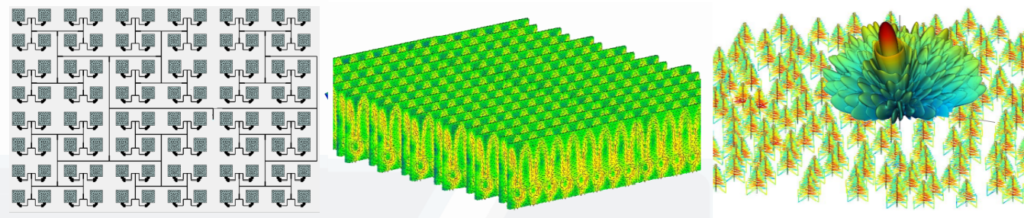
The transducers that are the elements of an array antenna can consist of very different designs. On the left is an array of patch cells, in the middle a picture of an array formed by waveguides, while the right image shows a very large array (square kilometer) composed of many independent antenna masts.
Synthetic antenna array synthesis
When designing an antenna an engineer has several challenges to overcome including the size of the array they are trying to model. Antenna arrays that are kilometers wide or less than a centimeter long can both be large if we consider the number of elements it contains. Such arrays can include thousands of elements and therefore simulating all of them, at once, in a single simulation can be difficult and time-consuming. To overcome this, engineers simulate just one element via a thorough detailed full-wave analysis. This process not only ensures that the process is possible but it also yields an accurate result. The results from this single element are then synthesized to produce a full array, removing the need to simulate the entire array in one simulation.
Antenna array patterns
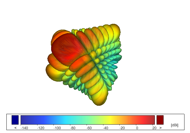
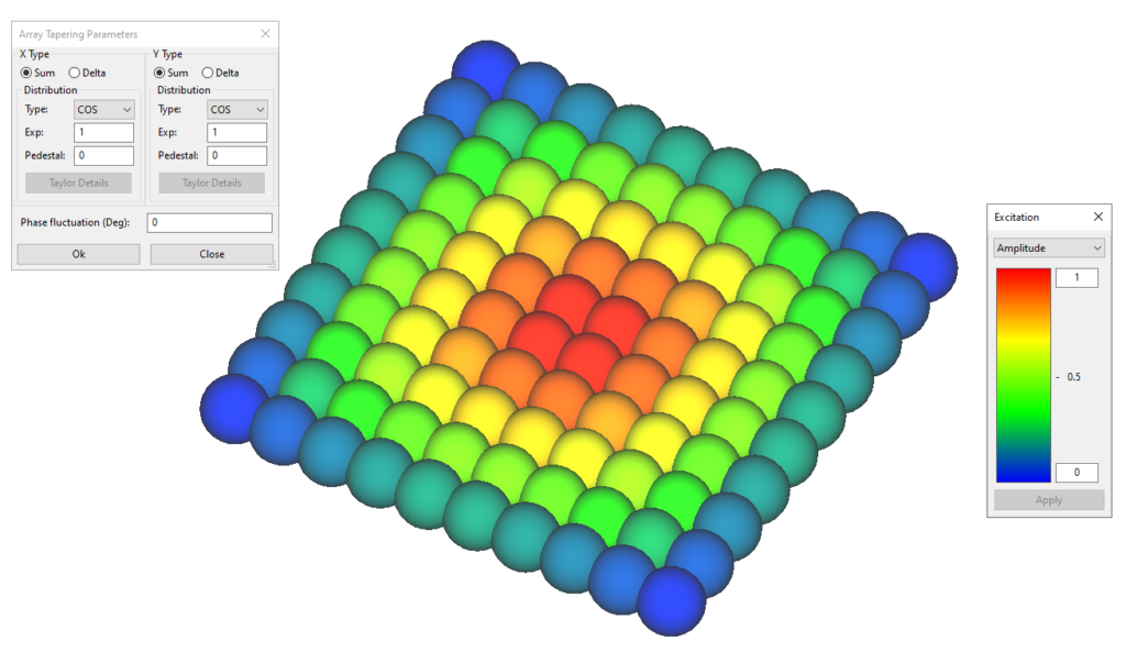
When synthesizing the single element into an array, the engineer can model array functionality by changing the pattern of the array. An engineer can achieve several array patterns by choosing one of the available schemes (rectangle, circular, distances, etc), and adjusting the array tapering (X-Y distribution, phase fluctuation). With just these simple inputs an engineer can synthesize an array extremely quickly.
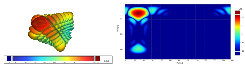
Once the array is synthesized the engineer can check the pointed beam and corresponding coverage maps.
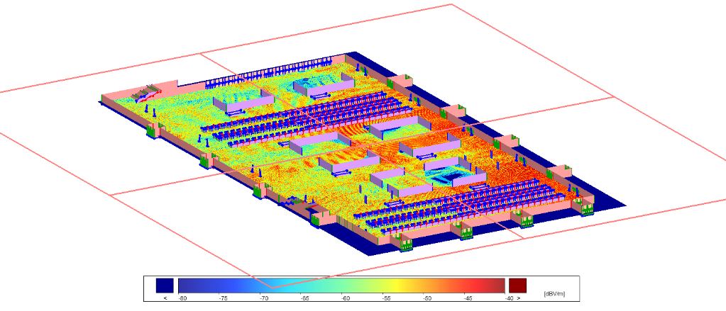
Now the engineer can produce a simulation of the signal but still does not know if they can receive the signal. To find out the antennas coverage they integrate their array into an operations environment by creating a simulation of the environment, such as the factory floor shown in the image below. In this image, we can see the EM coverage inside the entire factory that has resulted from our antenna array.
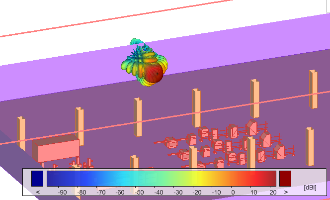
We can also zoom in to our antenna to see its integration into the model, including its beam orientation, as shown in the image below.
Summary
Antenna arrays will form the cornerstone of wireless communication in the years to come. Engineers will face the challenge of designing individual elements, patterns of arrays, and the installations of arrays. With Simcenter 3D an engineer has access to the specific functionality required to address these challenges.