Getting started with Animation | NX Tips and Tricks
Introduction
Welcome! If you’re new to our Tips and Tricks series, we’re focusing on new capabilities added to the June 2023 release of NX™ software, and how you can implement them into your workflow. Today, we’re taking a look at animation, and how to setup your mechanism using NX Animation Designer. Before we dive in, let’s remind ourselves of Animation Designer 👇
What is Animation Designer?
A motion analysis application for studying the kinematic behavior of designs. Studies can be done at the conceptual level, including 2D free body diagram sketches and simplified 3D models.
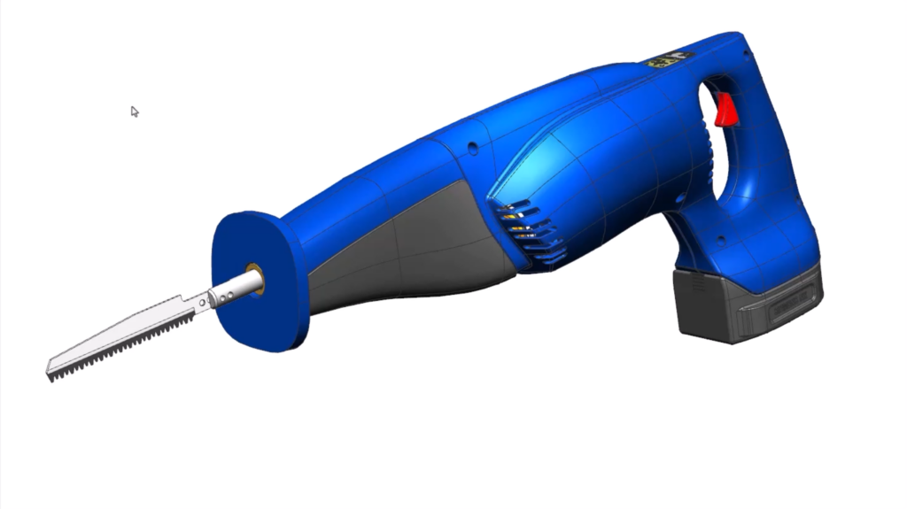
Our focus throughout the course of the blog will be on this electric Saw. We’re going to use tools within NX to create motion for the Saw. To start, simply open the Animation Designer tab; it really is as simple as that.
How to create Rigid Groups
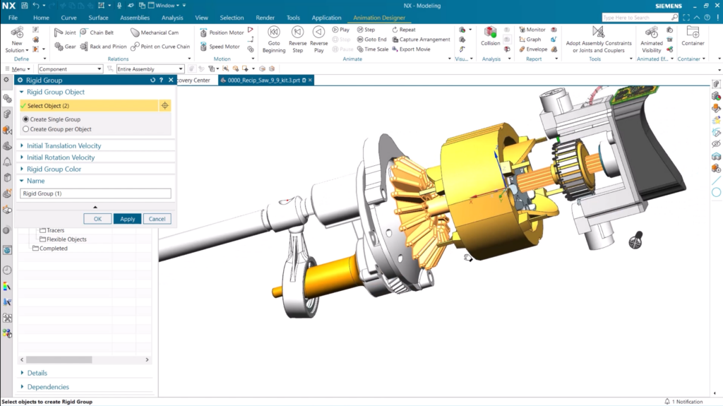
At this point, we’re now ready to start creating the animation for the Saw, and we’ll do this by creating Rigid Groups. These Rigid Groups will allow the components of the Saw to move in the same way, ensuring its performance is as efficient as possible. When creating a Rigid Group, we need to remember to add components that are going to rotate/move together for the model. With that in mind, we’ve put the fan and the motor shaft within the same Rigid Group.
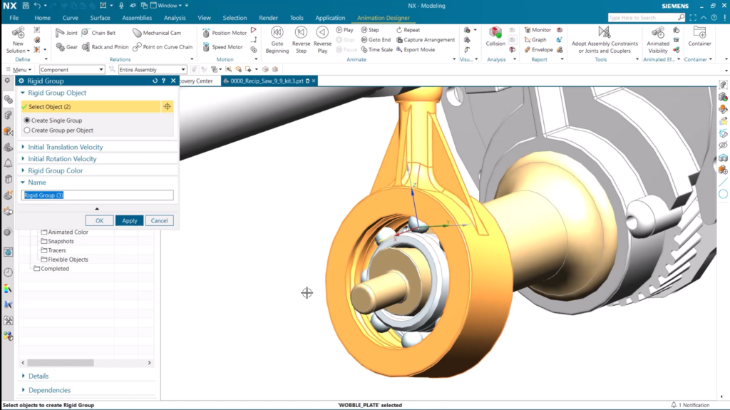
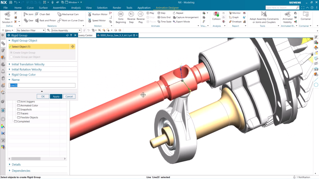
It’s also possible to add other elements to a Rigid Group too. For instance, we can add a sketch line to our Rigid Group, as well as the Saw blade and shaft components. This flexibility enables complete control when creating Rigid Groups, enabling us to optimize the performance of the final product.
An important tip:
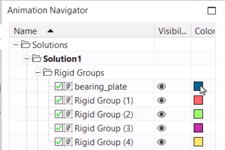
It’s possible to view one Rigid Group by utilizing the Rigid Group color functionality. This will display all your rigid groups within the Animation Navigator
Placing joints between Rigid Groups
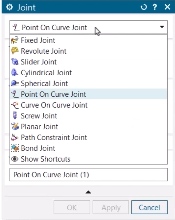
Each Rigid Group is going to move independently of one another; it is only until we add joints that they’ll be able to influence one another. Here are the types of joints you can add within NX:
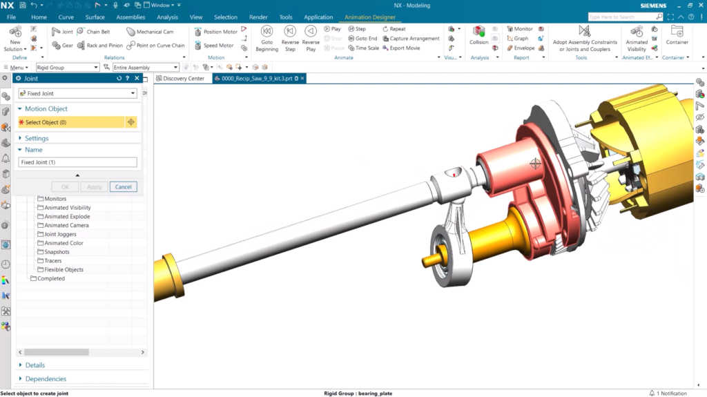
For the Saw, we want to start by adding a Fixed Joint; this will allow the other Rigid Groups to move in reference to it. For the Saw, it’s a case of selecting the base of the Saw shaft so that the other Rigid Groups will be influenced by its movement.
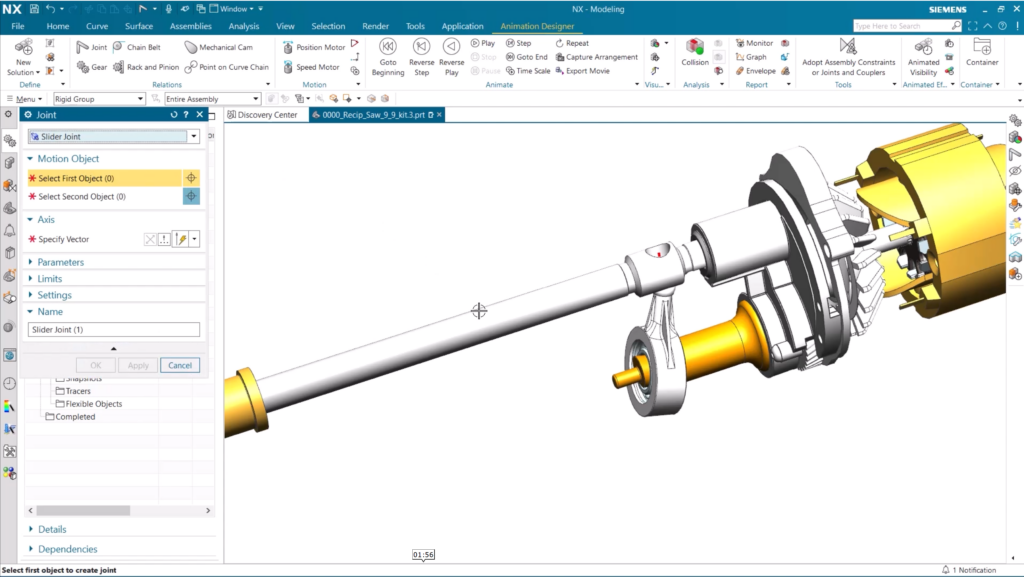
With that done, we can go ahead and add a Slider Joint; this will enable the final motion of the Saw to move back and forth. To add the Slider Joint, we need to select the Rigid Group that will move, and the Rigid Group it will move in reference to. In this case, it’s the component we’ve created for the fixed plate from earlier.
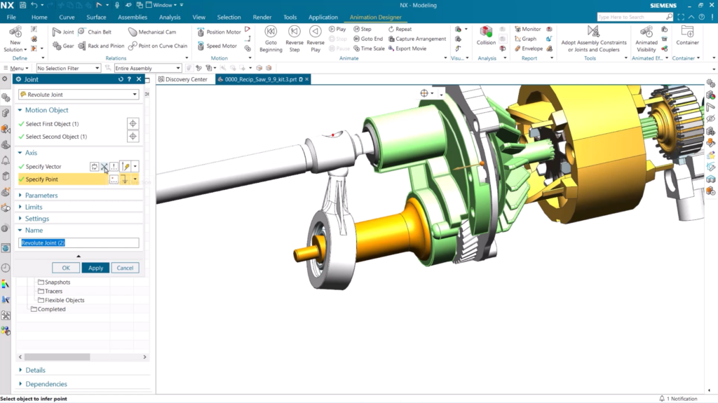
Next, we can add Revolute Joints. A Revolute Joint connects two motion bodies, or one motion body with a Fixed Joint to allow for one rotational degree of freedom. For our Saw, we want to add a Revolute Joint between the wobble plate and the wobble shaft. Both of these Rigid Groups will be moving, so the motion from the wobble shaft will be transferred to and influence the motion of the wobble plate.
Adding gears and motion
With the joints placed, we’re now in a position to add gears and motion to our Saw. This will allow the power of the motor shaft to be transmitted to the wobble shaft via their different joints. There is the option to add different gearing ratios, but for this instance, we will keep the ratio 1:1.
The final product
And here’s the final product. Our Saw is created, and we can view the motions from the joints and the motor.
Continue your journey with NX
Be sure to continue your journey with NX by clicking on the call-to-actions below. Thanks for tuning in!
Watch the Get started with Animation video here ▶️
Take me to the NX design blog 📚


Contact the NX team today 📲