An Automated Solution for Voltage-Aware DRC
By Dina Medhat, Mentor Graphics
Automated voltage propagation with Calibre PERC makes it easier to comply with voltage-aware DRC spacing requirements

Metal spacing rules are normally defined in the design rule checking (DRC) sign-off deck, and are purely geometric. This has been a fact for, well, forever, known to even the most novice verification engineer.
Now though, the more advanced nodes have brought with them a new kind of spacing check, called voltage-aware DRC (VA-DRC).
What does this term mean, and what new challenges does it bring to the DRC task?
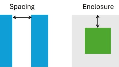
With VA-DRC, designs must comply with complex spacing rules that require variable spacings based on either the operating voltages, or the difference in voltages between lines running next to each other.
Because voltage controls these metal spacing rules, designers can no longer apply just one spacing rule per metal layer. However, using traditional verification tools, the challenge is obtaining the voltage information on the nets quickly and accurately so the designers can apply the appropriate spacing rule.
Let’s talk briefly about these voltage definition challenges.
The well-known method is to add markers with the voltage value to the layout. These markers can be text layers or polygons. However, markers are a manual process, and as such, they are both time-consuming and subject to human error.
Additionally, the complexity of the voltage-aware rules intensifies the necessity of accurately defining voltages in a layout. Checking errors that are introduced during DRC because of improper rule coding or erroneous voltage markers can generate hundreds of errors that must be analyzed and debugged.
False DRC violations will then need to be waived by the designer, which introduces even more overhead. Also, inaccurately marked layouts can result in substandard routing optimizations if the router uses a general worst case rules, rather than rules based on the actual voltages present on various nets of the layout.
The best way to address VA-DRC challenges is through an automated flow that can propagate realistic voltage values to all points in the layout, eliminating the more fallible manual process (Figure 1). This VA-DRC flow should not require any changes to sign-off decks, and it should generate the voltage information automatically, without requiring the designer to manually add any physical layout markers.

Figure 1. Automated VA-DRC flow
This type of automated flow for performing VA-DRC can be established based on a tool like the Calibre PERC reliability solution.
The Calibre PERC flow (Figure 2) first identifies the supply voltages for the design, and then uses a voltage propagation algorithm to determine the voltages on internal layout nodes. Voltages are computed automatically based on static propagation rules, which can be user-defined for specific device types. The algorithm is applied to the netlist to identify target nets and devices needed for VA-DRC.
Because the netlist information is preserved along the entire flow, the results are context-specific, making them easy to debug. This integration between netlist, connectivity-based voltage analysis, and geometric analysis is what enables a comprehensive solution to VA-DRC challenges.
Once the node voltages are computed, the Calibre PERC tool writes out the voltage information as text markers into a separate file, which is provided as an input to the Calibre tool running the DRC sign-off deck.
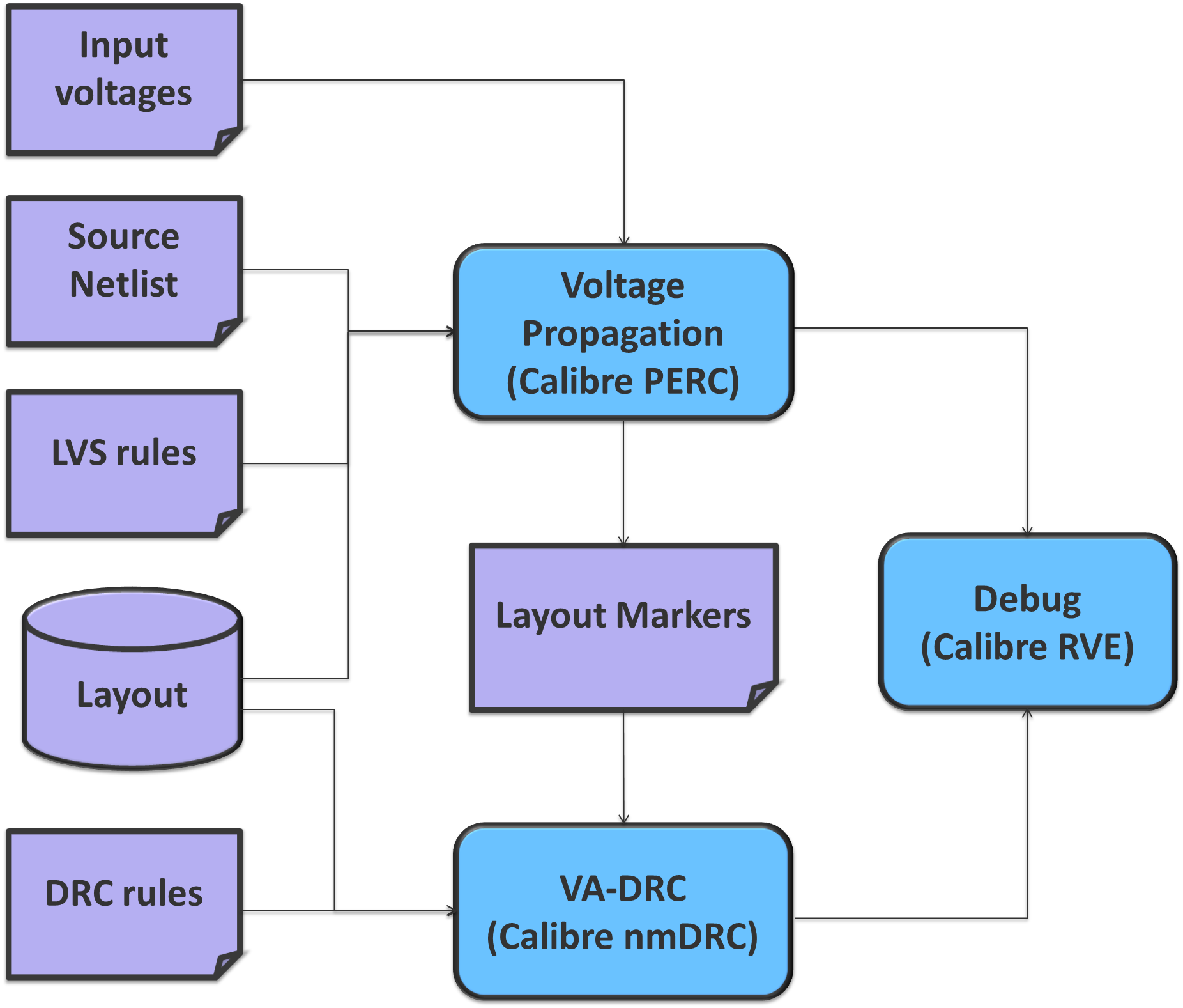
Figure 2. Automated VA-DRC using the Calibre PERC tool.
As an example, we implemented a VA-DRC flow using the Calibre PERC and Calibre nmDRC tools for the VA-DRC analysis, and the Calibre RVE results debugging environment for viewing and debugging the results.
This type of debugging environment enables the user to debug results from both the geometric perspective and the topological perspective (for voltages propagated to internal nets), as shown in Figures 3 and 4.
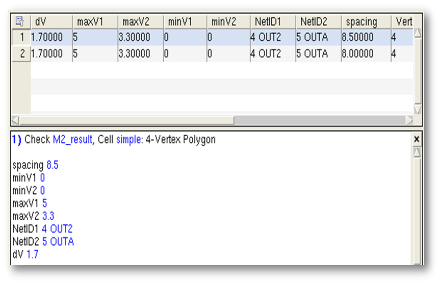
Figure 3. Geometrical view of the results.
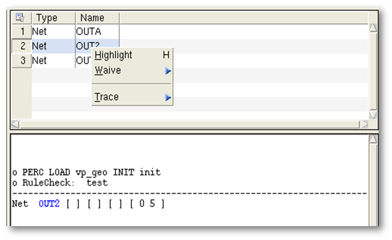
Figure 4. Topological view of the results.
Moreover, interactive debugging is an important aspect in this flow.
Designers can trace these voltages automatically to identify their origin in the design. This combination of physical and electrical information is very useful for both the designer and the layout engineer when qualifying results.
Figure 5 demonstrates voltage tracing information generated from the Calibre RVE tool between one of the internal nodes and the supply voltage.

Figure 5. Voltage tracing information
VA-DRC is just one example of the challenges designers face at advanced nodes. As designs and design rules grow more complex, new solutions must be developed to ensure continuing manufacturability, performance, and reliability. Continual innovation is essential to success.
Author
Dina Medhat is a technical lead for Calibre Design Solutions at Mentor Graphics.

Liked this article? Then try this –
White Paper: Improve Reliability with Accurate Voltage-Aware DRC
This article was originally published on www.eetimes.com