Why are power transformers so noisy?
Power transformers are noisy!
As shown in this energizing video of a 120 MVA power transformer.
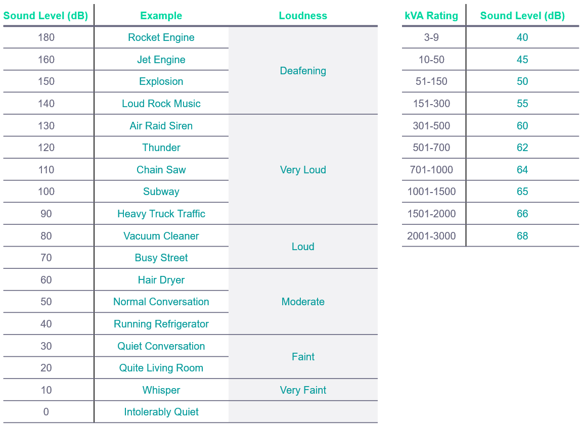
This noise, known as the transformer hum, is so loud that mandatory personnel must wear protective equipment in power substations. Near residential, commercial, and medical facilities, the noise is unbearable. It is like running a hair dryer or a vacuum cleaner 24-7! Tables 1 and 2 contrast the transformer hum with known ambient sound pressure levels in decibels (dB). We can see that the quietest transformer makes a similar amount of noise to a fridge. As the power rating increases, so does the noise level, until it is equivalent to that of a vacuum cleaner.
Consequently, installing transformers near people without protective equipment must meet stringent noise emission requirements. To avoid over-engineering, the transformer hum needn’t be significantly less than the sound levels of other local equipment, such as cooling fans. The rating, design, assembly, and installation affect the sound level.
What is Cold-Rolled Grain-Orientated Electrical Silicon Steel (CRGO/GOSS/GOES)?
Adding silicon to steel increases the electrical resistivity of iron, reducing the eddy current losses. For transformers, unidirectional permeability is desired. This is achieved by orientating the crystals and grains in the material. As a result, the flux permeates easily in the orientated direction with the application of an external field. The material is thinned using cold rolling to align the crystals. This has two advantages over hot rolling: Firstly, it aligns the crystals in the direction of the rolling, and secondly, it makes it possible to make the material thinner. Thinner layers of steel sheets separated by an insulating layer further reduces eddy currents.
What causes the transformer humming?
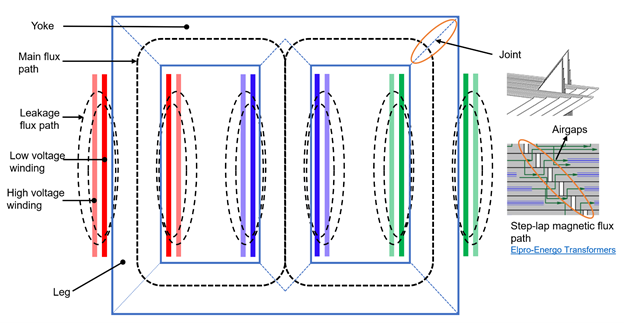
To understand the transformer hum’s sources, we must first appreciate the structure of a transformer. Figure 1 shows a three-phase transformer. The phases A, B, and C (or U, V, and W) are wound around one of the legs, corresponding to the red, blue, and green bodies in the image below. The main magnetic flux path is well-defined and unidirectional. We apply this advantage to maximize the transformer power density by using unidirectional (anisotropic) electrical steels. These are cold-rolled grain-oriented electrical silicon steels (CRGO/GOSS/GOES). These are electrical steels engineered to permeate flux efficiently only in one direction at an even lower loss. At the corners, we see that the flux must change direction, forcing it through the non-optimized direction. To deal with this, the core is split into the top and bottom yokes, and the three legs use specially designed joints. Transformer joint design as seen on the right of figure 1 is a worthy engineering challenge. It affects the losses, noise, and assembly.
What is magnetostriction?
The price we pay for using grain-oriented steels is higher noise levels. In general, when a ferromagnetic material is exposed to a magnetic field, it experiences mechanical stress that it relieves by changing shape. This change in shape due to forces induced by the magnetic field is magnetostriction. The deformation is either positive (lengthens), which is the case for iron, or negative (shortens), as experienced in nickel.
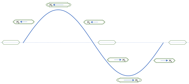
In figure 2, as the applied field increases, the limb (yoke or leg) undergoes tension and elongates which is maximum as the field peaks. As the field decreases, the elongation also decreases. In the negative half-cycle, the deformation process repeats, although the field is reversed (if we neglect hysteresis memory effects). Magnetostriction, therefore, occurs at twice the grid frequency, i.e., for every electrical cycle, there are two magnetostriction cycles. Other permeable transformer elements like shields, clamps, and tanks also experience magnetostriction from leakage (stray) flux exposure. Now we can consider the effects of magnetostrictive forces in the new 2212 release of Simcenter 3D Low Freq EM.
Although it happens in all ferromagnetic devices, why is it associated with transformers? Simply because of the core material. Grain-oriented electrical steels permeate more unidirectional flux for the same applied field as the non-oriented (isotropic) steels. Isotropic steels are used in rotating electric machines. Hence, grain-orientated electrical steels experience higher magnetostriction and sound pressure levels.
Is this the only source of transformer noise?
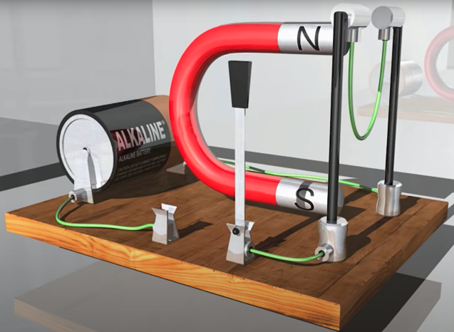
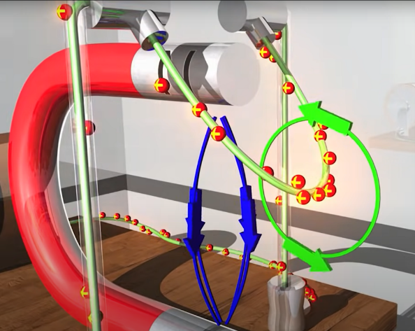
From figure 1, you notice that the transformer windings are a major part of the transformer. They too experience a force known as Lorentz or J x B, where J is related to the current and B to the magnetic field. If you place a conductor between the poles of a horseshoe magnet and rest it on two parallel conductors where it is free to roll, and then complete the circuit using a battery and a switch. Immediately you flip the switch, the conductor will roll off in one direction until it is outside the reach of the magnetic field. In much the same way that the loose wire is displaced in the images below. It experiences Lorentz force caused by the current flow in the presence of a magnetic field.
Transformer windings also experience this as they conduct current in the presence of the core, leakage, and winding (self and mutual) fields. Although bolted, some deformation of the winding structure still occurs, repeating at twice the grid frequency. In addition to noise, Lorentz forces are often the reason for the winding structural failure. As is often the case when a system short-circuits and the current increases to several times that of the rated current.
Conductive transformer structural elements like shields, bolting, and clamping systems are also subject to Lorentz forces. They are exposed to leakage and stray fields, which induce eddy-currents resulting in Lorentz forces. Reducing leakage and stray fields is an ever-present challenge in transformer design.
With our new knowledge, let’s revisit the transformer joint seen on the right of figure 1. It is important to notice the air gaps. They interrupt the flow of magnetic flux setting up an attractive force between the steps, just like when a gap separates two magnets. This is compounded by the magnetostrictive effects and the higher flux leakage. The attractive or repulsive force is known as the magnetic or Maxwell force. The transformer joint design complexity is addressed by looking at both the EMAG and the force contributions.
How is transformer noise analyzed?
The 1300 kVar reactor seen in figure 3 was simulated in the new release of Simcenter 3D 2212. In the low-frequency EM (EMAG) environment, the magnetostrictive characteristic curve was defined from strain and flux-density. After setting up the EMAG problem, the forces of interest based on the bodies they act on, in this case, the core, were requested and extracted simultaneously during the solve. They were then exported to the Simcenter 3D Acoustics solver. Physics-specific secondary geometric and mesh models were derived and associated with the same primary CAD. Consequently, any CAD changes are automatically inherited, saving the time that would otherwise be spent manually accommodating any new geometric changes.
The field results of figure 3 are the flux-density, magnetostriction forces, and the corresponding acoustic pressure, all in Simcenter 3D.
Up to this point we have only looked at the EMAG sources of noise, which apply to naturally cooled transformers. For forced cooling using fans, it is important to consider both the EMAG and mechanical (e.g. fans) sources in noise analysis, as illustrated in figure 4.
How simulation helps
Power transformer development is a multi-objective (cost, time, quality) process that equipment manufacturers must get right the first time. This is because, in the energy and utility industries, the physical prototype is the product. In these industries, physical iterations are really expensive. Manufacturers must therefore understand the transformer behavior as quickly as possible. The new release of Simcenter 3D 2212 provides this physics-based insight into transformer behavior. That is EMAG, structural, and acoustics engineering challenges in one CAD-centric multi-physics platform with traceable workflows. That is, the different physics attributes (EMAG, structural, and NVH) are verified ensuring overall product performance. This avoids over-engineering based on a single physics. Maintaining geometric links to a reference primary CAD model propagates geometric changes automatically, keeping the simulation (CAE) results up to date and ensuring their relevance in product development decisions. Traceability standardizes processes, speeding up workflows by reducing the chances of duplicating tasks unnecessarily, and enhancing collaboration across multiple teams.