How can you get better boundary condition inputs for your whole engine model?
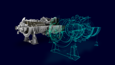
In our previous blog, we talked about how the whole engine model (WEM) can be used in the gas turbine industry to accurately calculate the transient thermo-mechanical behavior of a gas turbine engine under a wide range of operational scenarios. This has clear implications for the lifetime of the different components within the engine as well as the performance and efficiency of the gas turbine itself. But how can we have confidence in what we are calculating?
Like any simulation tool, if the inputs are garbage, we should not expect a lot from the results! So how do we ensure that our inputs are of the highest fidelity?
Gas turbine original equipment manufacturers (OEMs) have generated a large amount of know-how and understanding of their respective engines over the years through extensive simulation, trial and error and test or validation campaigns. The steady-state or baseload/cruising status of an engine is critical to understand the performance of the engine. However, the challenge is how the engine got to that state: what sort of temperature loading and gradients the metals experienced to get to that steady-state condition. In order to understand this, the heat transfer coefficients (HTCs), the fluid temperatures and thermal fluxes are critical pieces of information to build and understand the evolution of the thermal state of the gas turbine over an operational scenario.
Capturing the status quo
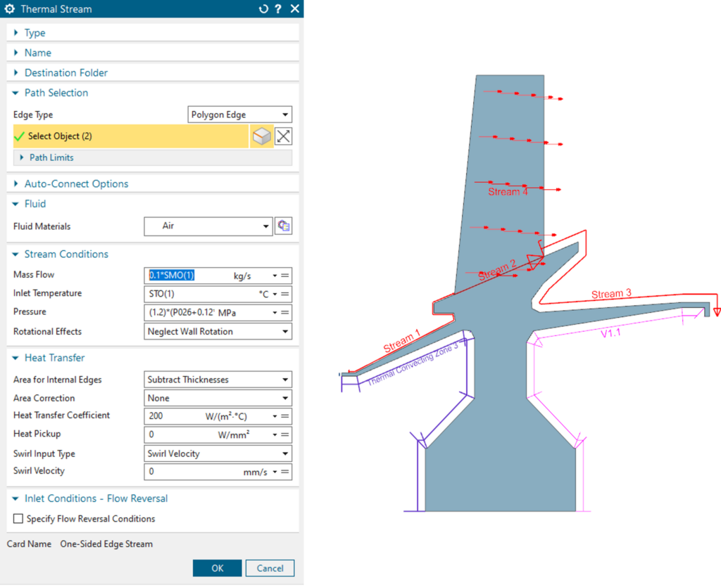
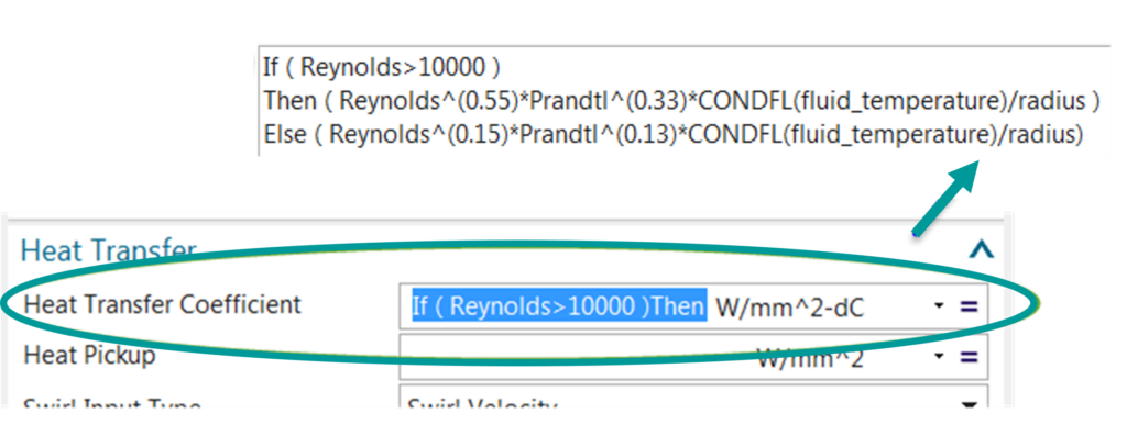
Figure 1 is an example of a thermal boundary condition input window for the turbine-specific stream boundary condition. This is where companies can capture the proprietary know-how of their engine: how the temperature and pressure of the stream evolves as the gas turbine ramps up, reaches baseload/cruising speed and altitude and subsequent ramping down or landing. A crucial input for the metal temperature calculation is the heat transfer coefficient: the driver behind the evolution of the metal temperature across which this boundary condition is placed. In the simple example above 200W/m2.C° is chosen. In reality, as the main physical parameters of the convecting fluid (pressure, flow rate and temperature) evolve over the engine operation, it is pertinent to account for the changing physics involved. Below a certain rotational speed, the flow is not convected through the engine, which can lead to a different heat transfer process. The whole engine modeling process can account for this phenomenon in the boundary conditions in two ways (see Figure 2):
- Incorporation of if/then statements in boundary condition input fields
- Links to the key parameters from the mission/operational cycle that evolve over time
In addition to the above possibilities, typical heat transfer correlations like the flat plate correlation, the Nunner correlation, the Dittus-Boelter equation or some derivative thereof can be included as time or input-varying equations into the heat transfer correlation input window. It should be noted that companies are able to write company-specific plugins that contain proprietary know-how and information that can be called within Simcenter 3D. This user-defined plugin function is a feature that allows Simcenter 3D users to utilize their proprietary correlations in modeling the physics of their simulation. Users can code the correlations in C++ using application programming interface (API) functions that give access to solver-computed quantities. These correlations can be subsequently used in Simcenter 3D when applying and defining the boundary conditions. The solver will compute the user-defined functions used in the expressions, such as heat transfer correlations, during the solve-time.
Gas turbines typically have cooling bores for the hotter turbine components or for directing flow from the compressor to the internal cavities of a rotor. Energy can be transferred to the fluid from such configurations. Windage can be defined as that component of energy that is transmitted from a rotor to the fluid. Simcenter 3D has two dedicated functions that can account for this extra energy:
- Windage rise for slanted and vertical surfaces
- Windage rise for horizontal cylinders
However, what happens when there is a new gas turbine engine configuration or when the OEM is early in the design phase of a gas turbine engine where only rough sketches or operational scenarios are known?
Systems engineering: accuracy and speed
This is where a systems engineering tool like Simcenter Amesim or Simcenter Flomaster is often employed by OEMs to define the main operation of the gas turbine before there is any computer-aided design (CAD) data available. These types of models that are built using existing libraries of components within the software are flexible and typically mature with the design as it evolves.
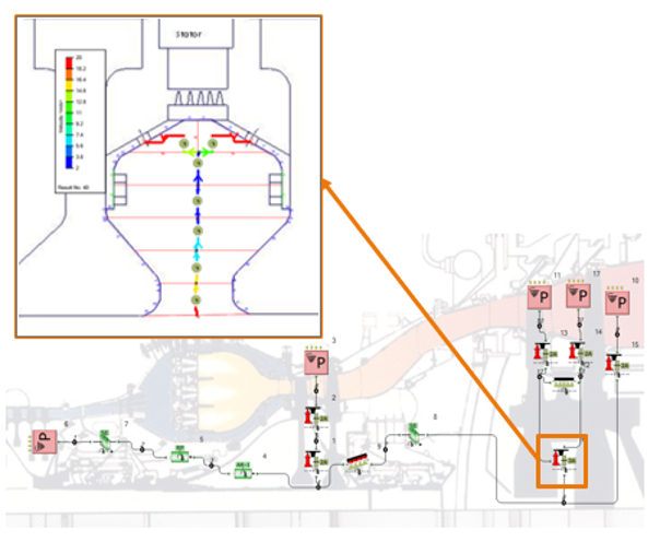
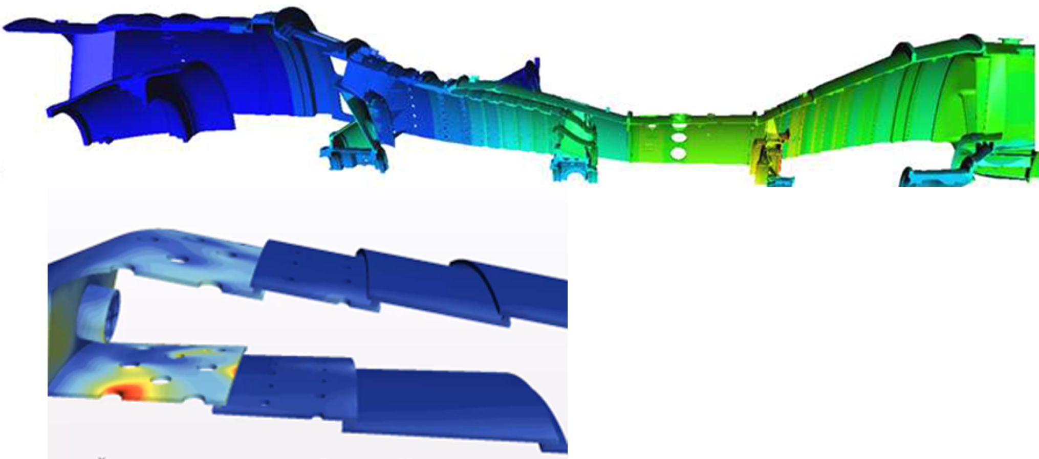
In the case of the gas turbine, being able to model and characterize the secondary airflows in and around the gas turbine is key to understanding the performance and efficiency of the whole engine. Secondary airflow is that portion of the airflow taken from the hot gas path at various compressor stages and utilized for cooling or sealing in the hotter parts of the turbine section. This air needs to be utilized efficiently and optimally to minimize the impact on the performance metrics of the engine. Simcenter Flomaster has a dedicated library and solver suite for such simulations. Key physical information like swirl correlations relevant to the cavities within a gas turbine can be calculated and subsequently utilized as inputs in the boundary conditions in the whole engine model (see Figure 3). Similar to the WEM practice of incorporating in-house knowledge and experience, Simcenter Flomaster offers templates for swirl correlations enabling companies to tailor the solution to reflect their best practices and methodologies. Simcenter Flomaster also contains scripting capabilities so a company can incorporate its own correlations for the systems-level model.
These types of system-level models can provide early insight into the operation of a gas turbine engine, and the parameters calculated from the model can be utilized to adapt whole engine model heat transfer correlations. This type of weak coupling can also be extended where the clearance or deformation calculated from the WEM can be fed back into the systems model, enabling the engineer to understand this effect on the networked flow distribution. This approach is also relevant to simulate and understand the performance of labyrinth seals, typically employed throughout the engine to seal air and hot gas from the metal.
Capturing 3D flow phenomena for the 2D world
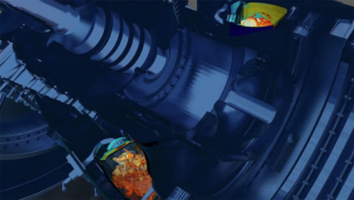
A second source of input for the whole engine model boundary conditions is computational fluid dynamics (CFD). CFD on the complete gas turbine is prohibitively expensive despite the recent advances in hardware and solver speed. However, it can still be employed to better understand local conditions and add more fidelity to the whole engine model. There are a couple of ways to use CFD in the WEM, but first, let us look at what CFD can elucidate for a whole engine model engineer looking at the gas turbine.
A gas turbine contains numerous areas of forced convection, not just the hot gas path. It is in these other locations where more information can be derived from CFD to better understand local flow and heat transfer conditions within a gas turbine; locations like the external extraction cavities, the cooling bores within a rotor, or the purge flows utilized to minimize or negate hot gas ingestion. These conditions could also be simulated and understood at time points other than steady-state flow, where local HTCs can have a significant effect on the heat transfer to and from the metal.
A whole engine model engineer can either incorporate a velocity-driven HTC into their model, in the thermal boundary conditions, or through direct HTC calculation from a conjugate heat transfer simulation in a tool like Simcenter STAR-CCM+.
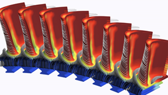
A second source of CFD input that can be utilized in the whole engine model is to add fluid domains directly into the 2D WEM. Since Simcenter 3D 2022, 3D fluid domains can be included in the axisymmetric part of the whole engine model (see Figure 5).
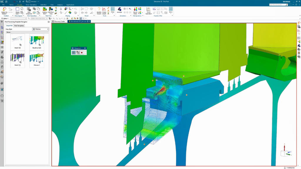
This area can be particularly sensitive to changes in temperature which may occur due to hot gas ingestion and adversely affect the mechanical lifetime of blade firtrees. To learn more about these capabilities, check out another WEM blog here.
As we have seen, there are a number of ways to help you populate the boundary conditions of your whole engine model. Depending on what stage you are in the development cycle, different levels of input fidelity can be used to help you better understand the performance of your engine and the subsequent impact on the metal temperatures and clearances of your engine.
You might be interested in…
Improving aircraft engine thermo-mechanical performance

Address the complexity of future aircraft propulsion systems with virtual engine systems integration
Leverage a digital strategy to improve hot section performance in gas turbine engine design