Utilizing CFD to analyze a PC Cooling System
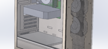
Here it is! Inspired by my own PC cooling system, I have designed the PC case to be used in our CFD simulations by creating case geometry using CAD. For CFD, I am using Simcenter Flotherm XT which is an electronics cooling CFD software that utilizes a CAD based enabling geometry engine, allowing for a seamless transition from model creation to setting it up for CFD virtual test studies.
The dimensions used in this model were measured by myself based on my own PC. Some of these dimensions were a bit tricky to measure due to internal wires inside the case getting in the way. However, this model aims to provide a good representation of typical gaming PC cases readily available.
PC cooling: How does this all work?
Well, 2 fans at the front provide forced airflow into the case, which then passes over the PCB and its components. The heatsink conducts heat from the CPU and transfers this to the passing airflow. The rate of heat transfer is amplified by the fan which sits upon the heatsink by increasing the rate of air flowing through the heatsink. The warm air is subsequently forced out via the fan at rear.
Setting up the CFD simulation of the PC cooling system
Once the PCB with all its components were inserted into the case, the model was ready to be set up. A steady state solution type was used to determine the temperature the CPU would eventually reach if the system was to run at a constant power. We decided to set the power sent to the CPU to be 65 W, as this was the average power the CPU received when I ran a stress test (Is My PC Too Hot?). The flowrates of the fan were adjusted to around 40 cfm which is more typical of PC cooling fans. Then we solved the model and let the magic happen!
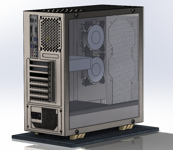
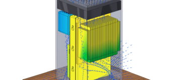
PC cooling system – Rear View
CPU temperature results
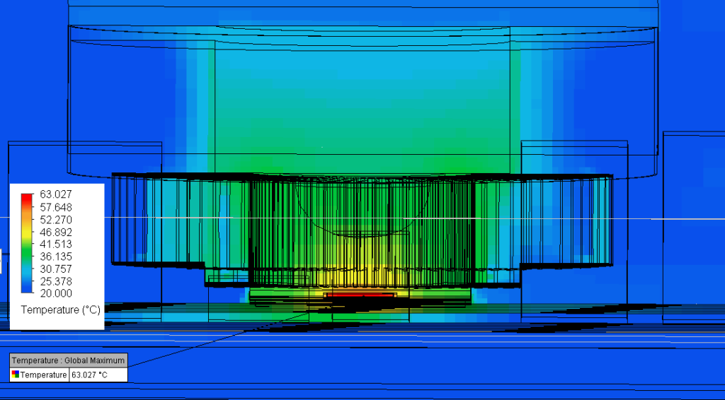
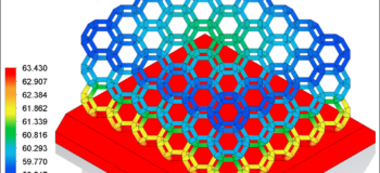
Maximum Simulation Temperature
The maximum temperature was recorded at the junction, inside the CPU, reaching 63 deg C. These results closely match those of a real PC I recorded (Is My PC Too Hot? ), and demonstrates the validity of the case set up. However, there is always room to improve.
What’s next?
Mesh refinement is a key area of importance in CFD simulations. In order to better capture the fluid flow both in and out of the PC vents as well as transferring of heat from the CPU to the surroundings, our next goal is to refine the mesh throughout the system.
If you would like to know more about Simcenter Flotherm XT, then try it out for yourself with a free cloud evaluation. The 30 day trial access features a variety of electronics cooling simulation examples.
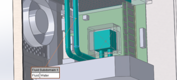
Water cooling: This pc cooling blog focused on CPU temperature prediction for an air cooled PC. If you are interested in water cooling for PCs, please see my further blog Using Water Cooling in Electronics Thermal Management.
For reference, my colleagues and I also have several related blogs connected to basic PC cooling evaluation:
– creating a CPU thermal model from scratch
– is my CPU too hot? comparing different PC cooling approaches
For more detailed simulation guidance on package thermal models, PCB thermal analysis or liquid cooling, I suggest you take a look at the the following technical presentations:
– On-demand webinar: Accelerate package thermal modeling
– YouTube Video: PCB electro-thermal modeling | a thermal and DC drop co-simulation approach
– On demand webinar: PCB electro-thermal and thermo-mechanical workflows
– On demand webinar: AI hardware thermal design – Liquid cooling of a Deep Learning Machine
Comments
Comments are closed.