Thor’s Hammer with a little Simcenter HEEDS-Ooomph!
Have you ever wondered what Thor’s hammer would look like if an Engineer and not two dwarfs designed it? No? Well please join me for a deep dive into the aerodynamics of Thor’s hammer.
I would first like to point out that I’m neither team Marvel nor DC comics. For many there are strong loyalties for one or the other, for me it is more about the movies and if they are good or not. However, I have to say that there are some characters I like more. But in anticipation of Stan Lee’s birthday on 28th December, I would like to take a look at one of my favorite characters.
I always found the Nordic legends interesting and therefore, seeing a company creating comics and movies out of the stories is a nice way to see how it would play out if it were real. One thing I always found fascinating with all the mythical and somewhat magical devices they have, having a hammer as a weapon is somewhat medieval-like. Considering a hammer doesn’t really have the best aerodynamics, yet this one behaves more like a boomerang? Also, how Thor is flying with it despite it being a big, super-heavy lump and yet still a light material (depending on your worthiness). I found I needed to look to see if an engineer could actually improve the design of the hammer.
What’s the KPI of Thor’s Hammer Mjölnir
In order to improve the hammer, we need to have a look what it is meant to do. Now according to Skáldskaparmál (poetic language), it is said that Loki challenged two dwarfs (Brokk and Sindre) to make a hammer and bet his head that they cannot create something as nice as the sons of Ivald (Ivaldesønnene). According to the book “The Younger Edda”, the hammer would always reach his target and hit it as hard as the bearer wanted. When Mjölnir is thrown, it would never miss or fly so far it would not find its way back to the wielder. It would also be small enough that it could fit into a coat or pocket.
Unfortunately, we cannot make it shrink. We could make it foldable, but that would cause issues with it being rigid enough when smashing it into something and not folding in on itself. We could compare it with some heat seeking or laser guided missile to make it always hit its target, but I wanted to have a closer look at the flying and smashing performance of Mjölnir.
It would need to have enough *oomph* and therefore enough volume with its hammer head, but also be aerodynamic enough to fly far and fast enough. I was also wondering how fast it should be able to fly.
After doing some online research, I found this website in which you can find 15 Things You NEVER Knew About Thor’s Hammer. One of them refers to the speed at which Mjölnir can fly, 770 mph (1,239 km/h), so roughly about the speed of sound at sea level and 20°C. The article states it is twice the speed of sound, but I guess the author was not an engineer and not hot on his math 😉
It also says that it is lower than the speed of light – dah – It’s about 0.00000115% the speed of light. So pretty much lower than the speed of light I would say (sounding geeky now?).
As you can see, it is not easy with a magical or mythical design to get the right product requirements from your customer. But let’s start from the current design. Judging from the size of Thor’s hand in the movie I derived the size of Mjölnir for the basic design. For the aerodynamics and the *oomph* the shape of the head and volume would be most important.
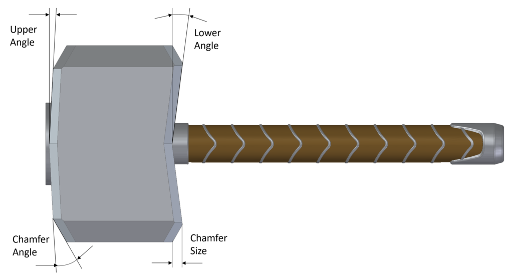
With that, I created the hammer head with two angles which can make the hammer head look either more like a pickaxe or like a two sided broad-axe from its side profile. I also added the chamfer angle and size that goes around the hammer heads smashing faces. These 4 parameters impact the aerodynamics as well as the volume.
“Simulating” My Mjölnir Throw
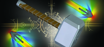
Although I’m not sure if I would be worthy enough to lift it, let alone throw it like Thor, I am, however, lucky enough to be worthy of wielding Simcenter FLOEFD. Creating the model in Solid Edge was fun and it looks nice. Now setting up the hammer to fly at 770 mph and creating a Simcenter HEEDS optimization study embedded in Simcenter FLOEFD is as easy for me (and for every design engineer) as throwing the hammer is for Thor.
Using the 4 parameters,
- I defined the maximum angles for the upper and lower head angle from -60° to +60° in 10° steps and
- the chamfer size from 0 to 30mm in 5mm steps and
- its angle from 10° to 70° in 10° steps.
- I set the output parameter to be the volume of the hammerhead to be maximized (for the *oomph*) but not bigger than 8 or smaller than 3 liters and
- the drag force to be minimized (or maximized as the force would point into the negative coordinate direction).
- I assumed that Thor would have enough strength to throw it hard enough or hit with the hammer hard enough and since it is a weapon, it should more hit than fly. So the weighting of the two criteria was chosen to be 1.5 for the volume and 1 for the drag force.
The only thing left was the selection of enough cores of my Laptop and simultaneous runs (3) and the total number of calculations (128) and then to just click on “Run” and let Simcenter FLOEFD do all the rest (meshing, solving and repeat) for each design variant the embedded Simcenter HEEDS algorithm comes up with.
OMG, what will it be?
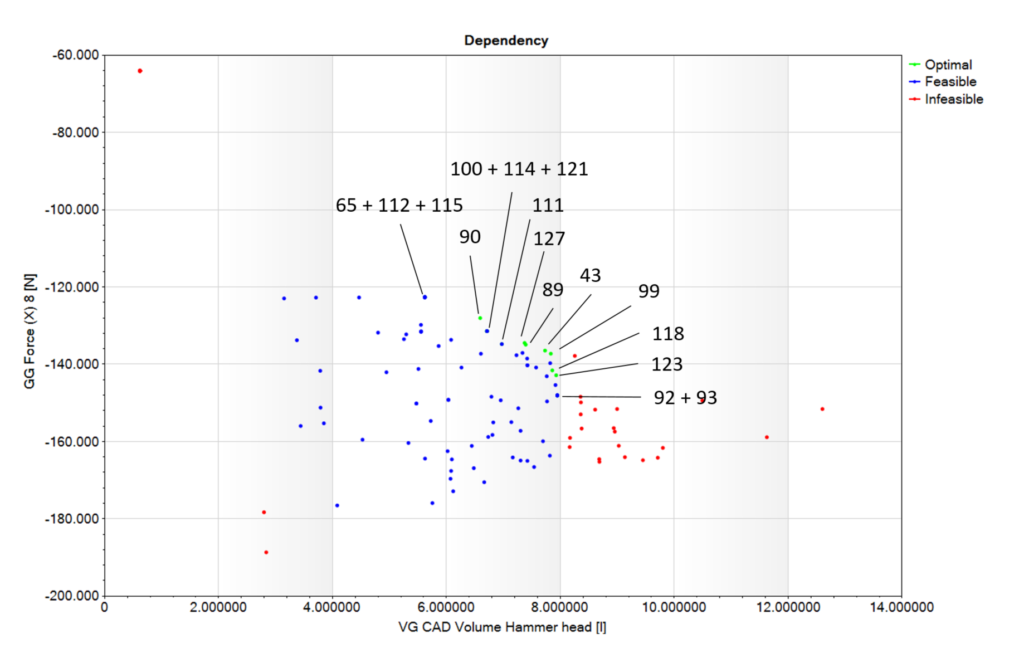
It took 2 days for the solver to run through 128 design variants and try to find the optimum cases that fit the criteria. The 16 Pareto front optimal points are shown in the graph below and some look blue (feasible) but they are a cluster of multiple similar ones and when zooming in you can see the separate ones. However, the values would be so close, that the difference is too little to make a big impact on the criteria.
By the way, I was running a 2D slice of the model with solution adaptive refinement to represent the shock front better. So the forces are for that slice but since the design change mostly impacted this cross section, the results are a good indicator of the designs suitability for Thor’s requirements.
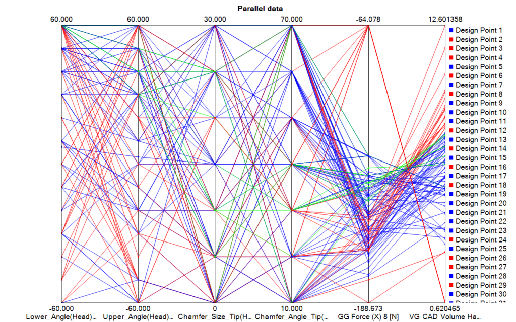
Looking at the parallel coordinate plot closer I was able to see that strangely the lower angle on the grip side of the hammer had all optimal points at 60° (pointing backward, toward the grip) – all of them. I would have figured the upper angle of course, as it will be more aerodynamic, but the lower angle was surprising.
The upper angle optimal points were all between 30° and 60°, so also pointing back towards the grip. Whereas the chamfer angle and size were all over the range in the optimal designs and had therefore probably little impact on the results.
And finally let’s have a look at the pressure, velocity and temperature plots. Every plot has its own range for the parameters. Most interesting is the temperature as the most extreme temperatures are +93°C and -104°C for the max and min. Yes, Thor better be heatproof.
Be the Hammer, not the Nail
Now with all the funky designs, the optimum might be some arrow pointy shape, but at the end of the day, I like the original hammer design the most.
And if you look at Thor’s fighting style you could imagine that his view is “If the only tool you have is a hammer, you tend to see every problem as a nail.” 😉
Have a great birthday Stan, may you be enjoying a large horn of mead in Valhalla, and great work with Thor’s hammer!


Comments
Comments are closed.