The rocket that refused to behave – The ultimate guide to spider element automation for rocket and aerospace structures
How one engineer wrestled misaligned interfaces, unexpected modes, and stubborn joints into submission — with help from Simcenter 3D
The first time the upper stage of the launch vehicle met the vibration table, everyone expected a smooth characterization test. What they got instead was a shriek.
A sharp resonance spiked far above predictions. Technicians flinched, and the stop button was fully utilized. The room fell silent except for the low hum of cooling fans.
The rocket was already fighting the team, and David, the structural dynamics engineer on duty, took it personally. He’d seen bad simulation models before, but this rocket was different. It was like it was designed to model something completely different. It insisted it was far stiffer than any physical measurement could justify.
Joints that live in a different reality
David dug into the digital model and immediately found the first culprit:
“The interface between two stacked cylindrical rocket sections had been represented as a continuous glue‑like surface connection, even though the physical attachment was through a series of discrete circumferential connection points“, David explained to us. “The digital model was created so that the structure was a perfectly bonded, perfectly rigid ring. The real hardware was nothing of the sort.“
His problem did not end there; worse, the meshes around the circumference of the two sections didn’t even align. Loads couldn’t be transferred cleanly. The rocket, physically and digitally, was living in two different realities.
The simulation never stood a chance of representing reality, and he had just completed an expensive test to prove it.
A problem shared is a problem halved
Some engineers may have tweaked parameters, adjusted boundary conditions, maybe smoothed over the discrepancy. David did something else:
He went after the real source of the problem, the connection definition itself.
He wrote to Siemens support engineers with a seemingly simple question, but it had some complex implications.
“Does your preprocessor support efficient creation of spider elements?”
David, Structural Dynamics Engineer
David’s plan was to find nodes in cylindrical space and pair inner‑diameter nodes with their matching outer‑diameter partners. However, he knew that, given the model’s size, it would take him half a lifetime to manually find and match each node pair.
Mark’s challenge
It was Mark, one of Simcenter 3D expert users, who got back to him.
“This situation was primarily an accurate geometry searching challenge in a cylindrical context. Simcenter 3D has very capable out-of-the-box capabilities, and it could deliver an out-of-the-box solution,” Mark told us.
He continued, “The user’s question asked if there were any ‘efficient’ methods, and I took this to mean automated tools or methods to deliver a solution. Usually, this is answered by Siemens staff with a simple “YES! It’s possible with NX Open”, but I wanted to put that answer to the test. Could I deliver an NX Open application that provides a complete solution for 100% of the use cases? And let’s be clear, Simcenter 3D could handle all the use cases individually, but this question was about efficiency. Could it efficiently create spider elements?”
Let’s take a look at the list of challenges Mark faced in answering this question and the answers he came up with.
- How can you identify a source node connected to N target nodes through geometric search in a cylindrical context?
Mark’s answer – Bounded volume selection recipes can find objects using cylindrical contexts
- Can you parameterize geometric searches?
Mark’s answer – Yes, with bounded volumes as rectangular boxes, cylinders and spheres, dimensions are editable expressions.
- Can you create a spider element (1 node to many nodes) as a rigid or constraint element?
Mark’s answer – The 1D Connection command has done this for maybe 2 decades
- How do you turn the steps a user makes into reusable code?
Mark’s answer – Journals can be recorded in NX and Simcenter 3D in multiple languages, including Python, Visual Basic, C++, and more
- As a very novice software developer (I’m a user after all), can I build a simple script that iterates inside a loop to make the out-of-the-box (OOTB) labor-intensive process free from significant user interaction
Mark’s Answer – Perhaps it is better if I show you
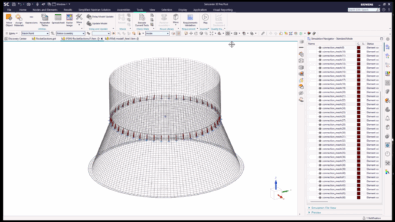
Mark provided us with the same videos that he sent to David, the first of which demonstrated the problem with the out-of-the-box solution. It shows the creation of a series of rigid connections around a cylinder. There are 240 connections in this model, from 240 nodes at an inner-diameter location to 720 nodes at an outer-diameter location. Each individual connection is from a single node to 3 nodes. All connected nodes have one thing in common: they all have the same angular position in space relative to a cylindrical coordinate system.
The next task is to automate the creation of those cylindrical connections as rigid or constraint spider elements. Mark documented this in his second video, but omitted another key tool in his engineering arsenal. Mark remains modest in his abilities and stated, “I have done this sort of stuff before in a very limited way using Visual Basic. But I know the trend is towards Python, and I decided to take this on using Python.” So he used GOOGLE to help him construct a loop in his journal. He then used it again to help correct the syntax and the variable definitions.
Armed with this new information, David began constructing spider elements.
With Python automation and Simcenter 3D’s NX Open layer, David scripted the creation of dozens, then hundreds, then thousands of proper discrete connectors along the rocket’s circumference.
Every spider captured the real load path.
Every node pair reflected the real geometry.
Every connection replaced a mistake and got a little closer to the truth.
The next battle: Modes that won’t line up
Fixing the interfaces helped, but the rocket model still wasn’t perfect. When David compared the new simulation to the physical modal test, the numbers remained off.
The frequencies were still too high.
The model was still too stiff.
Reality was refusing to match the digital twin.
David knew this was no longer a geometry problem.
This was a correlation problem.
The turning point: Letting the model learn
David explained the problem to Mark and fortunatly it was something he had seen before, infact he had presented a similar case at the NAFEMS conference. The primary difference was that in Mark’s case he worked on the transmission cover of an electric motor but the problem was the same, the simulation model was much stiffer than its physical counterpart due to the way the connection was made in the simulation model.

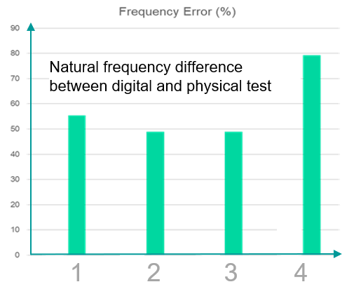
Mark’s investigations replaced the glued interface with discrete bolt locations which he then used a optimization process to find the effective diameter for each joint. This resulted in the frequency error being reduced from 58% to just 3%.
David launched a modal‑correlation workflow that blended simulation and test data. He ran iterative comparisons, extracted error metrics, and fed these into an automated design‑space exploration process using Simcenter 3D Design Space Explorer.
This process uses modern simulation tools to evaluate dozens or hundreds of parameter variations and iteratively tune the model until the test and the analysis are aligned.
Slowly, then all at once, the rocket’s digital modes began to shift.
The stubborn frequencies bent into place.
The shapes began to match.
The tuned joints behaved like their hardware counterparts.
Then, during the next physical test, the rocket stopped screaming on the vibration table.
The digital and physical rockets had finally agreed to exist in the same reality.
Fixing the model and improving the process
By confronting the problem at its source, including joint realism, circumferential discretization, automation of spider elements, and full test‑correlation loops, David transformed a misleading model into a reliable predictive tool.
He didn’t just fix the simulation.
He built a reusable methodology for future rocket stages, satellite separation rings, and any cylindrical interface where discrete attachments matter.
Simcenter 3D simply gave David the tools to close that gap, one spider connection at a time.
Other blogs that may interest you
- Stay uptodate with all the lastest simcenter 3D news with out monthly update – Simcenter 3D: The latest
- Discover how test and simulation can be integrated to better understand drive train package in – E-powertrain packaging validation: Tackling the “dynamic clearance” challenge with Smart Virtual Sensing
- See how you can leverage the power of multiple simulation tools in one package in – Multi-domain simulation – Unparalleled engineering excellence with Simcenter X Advanced


Comments
Leave a Reply
You must be logged in to post a comment.
Hey, nach einigen frustrierenden Casino Abenden wollte ich eigentlich pausieren, doch ein Freund erwähnte Freispiele und ich landete neugierig bei spin mama weil es für Spieler aus der Schweiz besondere Casino Boni gibt. Ich testete Gates of Olympus, verlor zuerst mehrere Spins und setzte dann etwas höher, wodurch plötzlich ein richtig guter Gewinn kam. Seitdem fühlt sich das Spielen dort viel lockerer an und ich schaue gern wieder vorbei.
Also, ich hatte mir vorgenommen, meinem Vater einen neuen Rasierer zum Geburtstag zu schenken, weil seiner schon total stumpf ist. Ich hatte eine furchtbare Pechsträhne, wo nichts klappen wollte, und dachte schon, ich muss umplanen. Dann habe ich bei https://sweety-spin.at/ eine ungewöhnliche Wette platziert, und plötzlich hat es geknallt. Der Rasierer ist da, und er hat sich riesig gefreut.