SimRod experience: Synthesize vibration profiles and create accelerated shaker tests

Nowadays, all test engineers are forced to execute their testing activities in shorter time since vehicle manufacturers are a in a very competitive situation to release their vehicles to the market. We, also as consumers, want less energy consumption, more durable vehicles with all technological improvements, and before anybody else has. Vehicle manufacturers need to reduce their development time to have a better position on the market.
By saying vehicle development, lengthy tests would be the first item that management want to reduce to achieve time and cost savings. (originally: considering duration itself and cost effect as a secondary reason.)
But, how can test engineers be sure that their verification testing (for example vibration fatigue testing on shaker) is set correctly, when they create synthesized vibration profiles and accelerated shaker tests? What if they do under-testing, which might lead to customer dissatisfaction and costly product recalls in the future? Or, what if they do over-testing, which might lead to high material cost, even longer test duration?
That’s correct that they can use standards. But, are these standards realistic enough? And can they have test specifications for each component on the car?
Efficient test tailoring would be the answer for all these questions. So, the test profile needs to be:
- Realistic – rely on real life conditions, rather than standards
- Accelerated
- Correctly determined – damage equivalent with real life conditions
WEBINAR
Realistic electric vehicle battery vibration testing
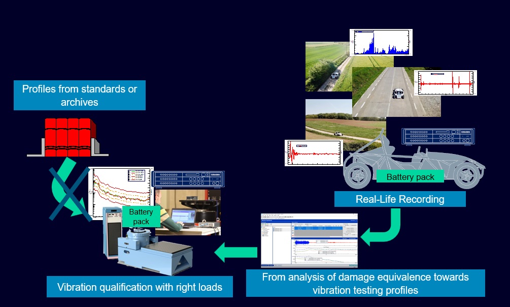
Let’s take an example of an engine mounted part that we want to test on a shaker. Assume that the vehicle life time around ten years. And we want to create accelerated (not 10 years!) and damage-equivalent test profile relying on real life conditions.
We can identify the workflow as shown below:
Tested on SimRod
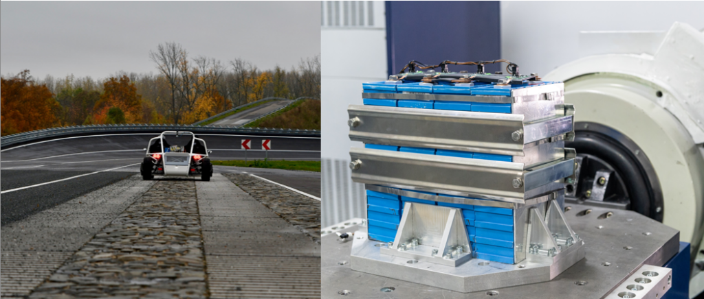
Some time ago, we have executed a data acquisition campaign with one of our electric vehicles on a proving ground in Aldenhoven, near Aachen in Germany. The vehicle that we tested, was a full electric sports car called SimRod (learn more about SimRod here). We use SimRod to better understand our customers and their need by carrying out same testing campaigns using the Simcenter test and simulation solutions.
We have instrumented SimRod to acquire data from a wide range of sensors. Besides, we also had some ICP accelerometers to assess structural behavior of a component on SimRod. We also created accelerated fatigue testing profiles for this component to be tested on a shaker. Keeping this information in mind, here are all important tasks step-by-step focusing on test profile creation.
1) Mission definition and data acquisition
First question we need to ask is “What will happen to my product once customers use it?”.
To answer this question, we need to first identify the operational environments of the vehicle. The example below shows four effective environments respect to distribution in total life time from a specific market.

We need to acquire relevant data from this different environments (missions). Typically, test engineers acquire vibration data from mounting locations of the test component to test it on a shaker. And they calculate Power Spectral Density (PSD) from acquired vibration data.
Simcenter SCADAS data acquisition hardware is designed to enable multi-domain acquisition campaigns to acquire analogue and digital data from a wide range of sensors including vibration, strain, force, displacement, microphone, video, GPS, temperature, pressure, voltage and so forth.
2) Analysis of damage potential
As previously said, acquired vibration data can already be used as an input to shaker table via PSD calculation. This refers to the bullet saying: ‘relying on real life conditions, rather than standards’. But, this is not enough to create a damage-equivalent and accelerated test profile. Now you may think: “How to quantify the impact of severe environments to my product?”
To better understand the impacts of different environments, we should go more into vibration fatigue, where we calculate the responses based on an excitation. So, we should focus on Fatigue Damage Spectrum (FDS), Maximum Response Spectrum (MRS) and Shock Response Spectrum (SRS).
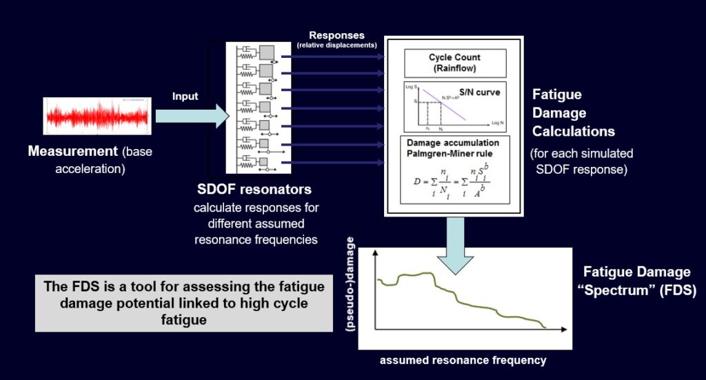
2-a) Fatigue Damage Spectrum (FDS)
The FDS is a tool for assessing the fatigue damage potential linked to high cycle fatigue. Assuming that the resonant frequencies from vibrations signal are considered as SDOF (Single Degree of Freedom) systems, where we take frequency and Q-factor damping into account. The responses (relative displacements) are calculated from each of these SDOF systems. As the next step, we can put these responses on an SN curve and calculate damage for each response. Thanks to Palmgren-Miner damage accumulation rule, we can accumulate these damage values. FDS diagram gives us assumed resonance frequency on x-axis and pseudo damage on y-axis. This diagram gives great opportunity to (damage-wise) compare different vibration loads.
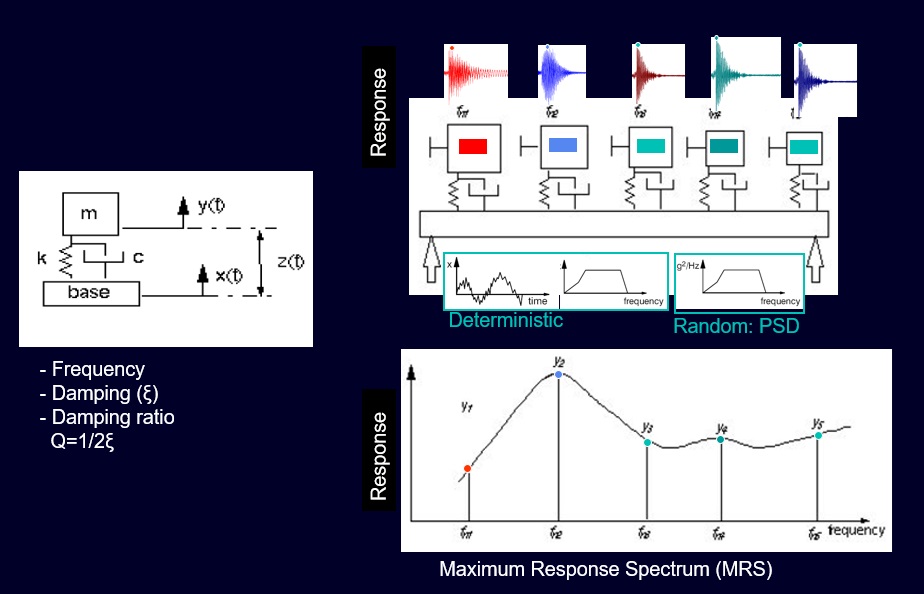
2-b) Maximum Response Spectrum (MRS)
As similar to FDS, MRS also considers assumed resonance frequencies as SDOF systems and calculates maximum responses from each of SDOF systems. This method is also very useful to compare different vibration signals. It’s also very useful as a controlling method, when test is accelerated. We can plot original data and accelerated data on the same MRS diagram. In this way we can see if the acceleration of the original signal shows some higher peaks on certain frequency. We should be very careful about this to avoid over-test the object.
2-c) Shock Response Spectrum (SRS)
SRS has a similar approach as the MRS method. But unlike the MRS – taking long-term steady state excitation in account, SRS focuses on extreme shock impacts. (For details, please check knowledge base article for SRS.)
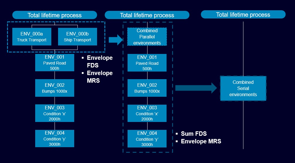
2-d) Calculation of Overall Damage
This process is to create a total lifetime test by considering different missions.
For example, if we want to count two different road conditions, we can sum FDS diagrams of the vibration loads. But imagine that the cars are shipped by truck or ship transport, and we also want to consider this impact. Then, we can envelope FDS or MRS diagrams to consider the worst-case condition for each frequency levels.
Simcenter Testlab enables MRS, FDS and SRS calculation via Mission Synthesis application. Mission Synthesis also gives the flexibility to better tune the SDOF systems.
3) Test profile synthesis
The last question you may have is “How to accelerate the test, but keep the damage?”.
This brings us to the test tailoring relying on the previous response analysis (FDS, MRS and SRS). Simcenter Testlab Mission Synthesis introduces test duration as user parameter, where synthesized profile will be adjusted automatically. Finally, synthesized profile can be identified as either PSD or sine sweep.
We can easily think of two use cases for Vibration Fatigue Theory:
- OEM perspective: OEM can use FDS to compare qualification evidence of potential component suppliers.
- Supplier perspective: Different OEM customers may give different qualification specifications (even with different types: PSD, sine sweep and different test duration…). Supplier can create single qualification test by comparing different qualifications.
Why Simcenter Testlab Mission Synthesis?
- Expectation for high quality, reliability and short test duration
- Different environmental vibration (e.g. transportation, road impact, engine induced vibrations etc.) during its life
- Under-testing will increase the chance of mechanical failure and add cost. Over-testing would lead to over-design and to over-cost.
WEBINAR
Realistic electric vehicle battery vibration testing
Questions? Let me know, I’ll gladly reply any possible question. Just drop me an e-mail safak.has@siemens.com.


