Green energies and hydrogen: Using simulation to design systems and coupling the system model to the PLC for control evaluation

Introduction
Renewable energies such as solar, wind, and hydro are experiencing rapid growth due to cost reductions, improved technology, and supportive policies. These energy sources generate electricity without CO₂ emissions, which is crucial for reducing dependence on fossil fuels and lowering emissions in the power sector.
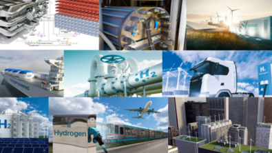
Hydrogen, specifically “green hydrogen” produced through renewable energy sources, is emerging as a clean fuel option. It can be utilized in industries, transportation, and energy storage, playing a role in decarbonizing sectors that are challenging to electrify.
The combination of renewables and hydrogen is vital for the global transition to a low-carbon economy, as it helps meet climate objectives and reduces greenhouse gas emissions.
However, the widespread adoption of green energy and green hydrogen poses certain challenges. This article focuses on how Simcenter Amesim, a System Simulation software, can assist in addressing these challenges, particularly when coupled with Programmable Logic Controllers (PLCs). Two specific application cases are presented: the coupling of a wind turbine and an electrolyzer for green hydrogen production, and the implementation of a hydrogen refueling station.
Both System simulation and PLC’s are crucial to support the transition to sustainable and efficient energy systems.
System Simulation
- Optimization
Enhancing efficiency and reducing costs by finding the best configurations and operations. - Integration
Ensuring smooth integration of renewable sources and hydrogen into energy systems. - Environmental impact
Assessing and minimizing environmental impacts. - Economic feasibility
Evaluating financial viability and supporting investment decisions. - Policy support
Aiding policymakers with data for effective regulations and standards. - Innovation
Accelerating development and deployment of new technologies. - Risk management
Predicting performance under various conditions to develop robust contingency plans.
PLC’s
- Hydrogen Production (Electrolysis)
PLCs manage the precise control of electrical current, water flow, and voltage in electrolyzers, optimizing hydrogen generation and ensuring safety by monitoring pressure and temperature. - Storage and Compression
They control hydrogen compressors and monitor pressure, temperature, and flow rates in storage tanks, ensuring safe and efficient operation. - Fuel Cell Management
PLCs regulate hydrogen flow, air supply, and power output in fuel cells, ensuring optimal performance in energy generation or vehicles. - Hydrogen Refueling Stations
PLCs automate the refueling process for hydrogen-powered vehicles, controlling flow and pressure to ensure safe and efficient fueling. - Pipeline Distribution
They manage hydrogen pipelines, regulating flow and pressure while detecting leaks to prevent accidents.
Different kinds of PLCs can be used for hydrogen applications, but one of the most advanced solutions is the the SIMATIC S7-1500 high-performance PLC by Siemens, designed for advanced industrial automation.
Its key features include:
- High Performance
Fast processing speed for complex automation tasks like motion control and real-time processes. - Modular and Scalable
Flexible configuration with various CPUs, I/O modules, and communication interfaces to suit diverse applications. - Integrated Safety
Built-in safety functions for controlling both standard and safety-critical tasks in compliance with safety standards. - Communication
Supports multiple industrial protocols such as PROFINET and Profibus for seamless system integration. - Diagnostics and Visualization
Built-in display and advanced diagnostics for easy troubleshooting and system monitoring. - Motion and PID Control
Supports direct control of motors and process variables with integrated motion and PID control. - TIA Portal Integration
Simplifies programming and configuration through the Totally Integrated Automation (TIA) Portal.
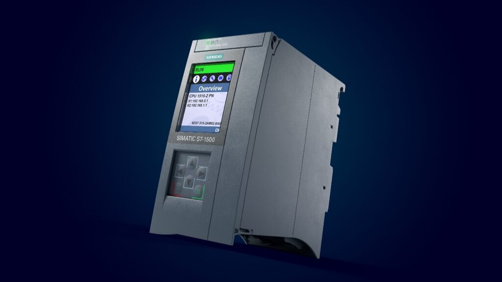
That makes the SIMATIC S7-1500 ideal for manufacturing, process control, energy management, and safety-critical applications, providing reliability, scalability, and security for modern industrial systems.
Then, connecting a physical model to the PLC that will be used in the real system makes it possible to evaluate and optimize controls at early-stage of the projects by:
- Testing various scenarios
Simulating various operational conditions to identify the best control strategies. - Analyzing performances
Enhancing efficiency and stability by being able to consider the performance of an entire system - Reducing costs
Finding optimal control settings without physical trials - Mitigating risk
Identifying potential issues and mitigating risks through virtual testing.
This finally leads to more efficient, reliable, and cost-effective renewable energy and hydrogen systems.
Any Simcenter Amesim model can be coupled with PLC controllers, either as what we call HiL or SiL.
In HiL, with Siemens Automation, the real PLC exchanges data with the physical simulation model using a simulation unit that is a simulated peripheral. With non-Siemens automation, the real PLC communicates with the physical model using the OPC UA protocol.
In SiL, the PLC automation is simulated (then it is a virtual controller). The data exchange with the physical model in Simcenter Amesim is realized differently depending on the controller type and if it is a Siemens or a non-Siemens automation.

Hydrogen systems simulation with Simcenter Amesim
How system simulation can help with renewables and green H2 production
System simulation is used to evaluate design options and quickly identify the best architectures of the system, helps to optimize the subsystems sizing and subsystems detailed design and the performance of the system can also be evaluated quickly considering many scenarios. You can predict how much electricity and hydrogen can be produced depending on the power sources sizing, it can be used to assess the best sizing of the energy storage system, even considering batteries ageing. Models can be used to integrate the electrolyzer stack with its Balance of Plant or to design innovative hydrogen storage systems.
Controls can be virtually validated and optimized, and the system is virtually commissioned thanks to a model of the physical system. It includes different levels of controls, from the high-level energy strategy to the component close controls. In the case of a wind turbine, a PLC can be used to optimize the yaw and the pitch of the blades and the generator power generation. With solar panels, controls can be used to adapt the panel’s orientation to the sun’s position. Many components from the electrolyzer Balance of Plant are controlled: the thermal management system with pumps and valves, the water supply system, the gas separation and storage systems…
Simcenter Amesim capabilities
To address the simulation of green hydrogen production and renewable energies, Simcenter Amesim comes with many features, such as:
- Library of components with validated equations:
- Electrolyzer electrochemical models
- Components for the modeling of wind turbines
- Solar panel models
- Battery models predicting the electrical performances
- Models for fluid sub-systems
- Multiple Gaz models for a large validity domain
- Detailed thermal effects models
- Fast simulations even for the simulation of a complete year
- Comprehensive post-processing tools to generate advanced plots, animations…
- Flexibility and customizable components for entering data sheets directly
- The State Chart controller can be used to define control strategies based on state machines
- PLCSIM Advanced connection to connect the physical model to a PLC controller
- Real-time capabilities…
Being able to leverage these capabilities will offer engineers several benefits when using system simulation:
Use case 1: Using renewables and electrolysis to produce green hydrogen
Design main challenges
Green hydrogen has been identified as an emerging solution to help decarbonize industries, transportation, and energy storage. But for an acceptability and large deployment of the solution, many challenges remain to be addressed, including:
- The initial investment (CAPEX) and operating fees (OPEX) must be competitive with conventional and other clean solutions.
- Green hydrogen must really and significantly reduce CO2 emissions, considering the whole life cycle, from production to usage.
- The fluctuant renewable sources and system location impact power generation, electrolyzer performances, and degradation.
- Energy and H2 storage systems can be integrated to improve the system’s performance.
- The system must be safe.
- The system must be reliable with limited degradation of the performance throughout its lifetime.
- Systems involve many components, physics, and controls and then are complex…
Simcenter Amesim standalone model for system design
To demonstrate the capability of Simcenter Amesim to model and simulate the combination of renewable energies with an electrolyzer to produce green hydrogen, a physical model has been developed. This model is composed of several sub-systems including:
- The wind conditions definition
Makes it possible to define fluctuating wind speed and orientation using real meteorological data or user-defined values. - The wind turbine power generation
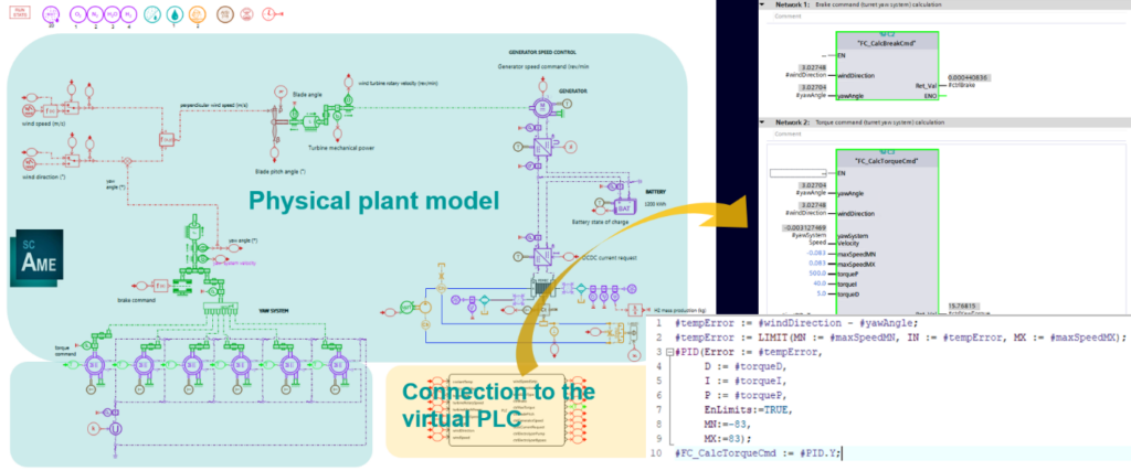
This subsystem model considers the wind speed and orientation, the wind turbine propeller characteristics, the transmission ratio, the generator, and power electronics to evaluate the dynamic power generated by the wind turbine. Several components are controlled including the propeller pitch angle and the generator. - The wind turbine yaw system
this one is used to align the wind turbine with the wind direction using 6 electric motors, a transmission, and a brake. Both the electric motors and the brake are controlled. - The battery energy storage system
A battery has been integrated into the system to absorb peaks of power generated by the wind turbine that exceeds the power that can be used by the electrolyzer. The battery can also help reduce electrolyzer power dynamics to improve performance and reduce degradation. Finally, the charged battery makes it possible to keep the electrolyzer running even when the wind stops blowing. - The PEM electrolyzer and its heat management system
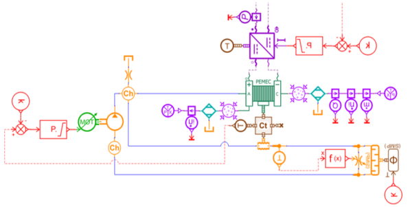
That includes a PEM electrolyzer electrochemical model, but also the DC/DC converter used to control energy flows between the electrolyzer and the battery, a water pump used to recirculate water at the electrolyzer anode side and manage the electrolyzer thermal behavior. The pump velocity is controlled to maintain the electrolyzer in the right range of temperature when a heat exchanger is removing heat from the fluid and a by-pass valve is controlled to by-pass the heat exchanger when the electrolyzer is cold. This model can capture the H2 and O2 gas production and the water consumption as well. It also predicts the electrolyzer performances including the electrical power consumption and the heat losses generating its temperature evolution.

Note that using this model to simulate a 1-day scenario usually just takes less than 30 seconds with a conventional laptop.
Example of simulation results
Thanks to this mechatronic model, simulations can be performed to capture the physical behavior of the different subsystems. We can for instance use it to:
- Capture the yaw system dynamic behavior
- Size the yaw system motors
- Optimize and validate the yaw controls
- Predict the yaw system power consumption
- Evaluate the pitch control strategy
- Predict the wind turbine energy production
- Size the fan, the generator, the gear reduction system, and DC/DC converter
- Evaluate different architectures
- Size the electrolyzer and the battery
- Optimize the system energy management
- Predict the electrolyzer dynamic performances and efficiency
- Predict the electrolyzer power consumption Predict H2 and O2 production
- Capture the electrolyzer’s dynamic thermal behavior
- Evaluate the thermal management system architecture
- Size the pump and the heat exchanger
- Optimize the electrolyzer operating temperature to reach the best performance when reducing its degradation


Connection of the system model to the PLC controller for control design and pre-commissioning
Then, the Simcenter Amesim standalone model that has been used for system design can be used to validate the PLC controls virtually and for virtual pre-commissioning. The controls are just removed from the physical system and replaced by an interface block, making it possible to connect inputs (control requests) and outputs (sensor measurements) to the PLC. The PLC can be real hardware or a virtual PC.
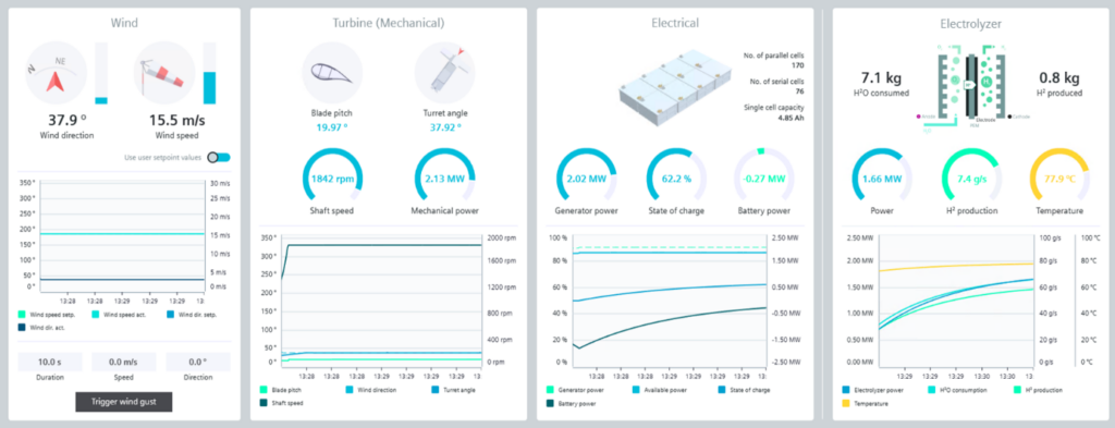
In our application, a virtual PLC has been generated using PLCSIM Advanced and connected to the Simcenter Amesim model thanks to Automation Connect. Finally, user interfaces have been created with the SIMATIC WinCC Unified System for visualization and interaction with both the physical model and the virtual PLC.
Then, it is possible to launch the simulation from the friendly user interface, which can also be used to visualize the system’s dynamic behavior with plots and animations. From the same interface, it’s also possible to modify the system’s operating conditions manually, such as the wind velocity and orientation of the ambient temperature. The parameters of the control strategies could also be tuned to improve control calibrations and system performances.
Use case 2: Hydrogen refueling station
Design main challenges
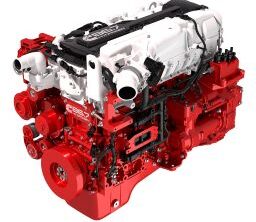
Fuel cell vehicles are starting to be more and more deployed, including mainly passenger cars but also trucks and buses. Combustion engines for buses & trucks could also burn hydrogen instead of gasoline or diesel. One of the limitations of a larger deployment of hydrogen vehicles (on top of the price, the life expectancy of the components, and the hydrogen storage…) comes from the fact that the hydrogen distribution network is still almost nonexistent. Several regions already started to deploy a larger number of hydrogen refueling stations in big cities and along the main highways and still have the plan to further extend the number of H2 dispensers.
One of the challenges with hydrogen refueling stations is to make it possible to refuel a vehicle in no longer time than for a conventional combustion engine vehicle. For a passenger, a 5-minute refueling time would be acceptable, while for a truck with a larger tank, 10 to 15 minutes would also be satisfactory.
Moreover, quickly compressing hydrogen generally raises its temperature. If the hydrogen comes to the tank with a temperature that exceeds values (usually 85°C) that could damage the tank materials. Then, several standards regulate the temperature limits for hydrogen when refilling a vehicle tank. And on top of that, for safety issues, flows and pressures must also be carefully monitored.

Finally, to make hydrogen refueling stations profitable, it is important to reduce the APEX and OPEX as much as possible. So, the system has to be designed with the best selection, design, and sizing of the components to contain the investments. The energy that will be consumed by the system, mainly for compression but also for thermal management, must be controlled and reduced as much as possible.
Simcenter Amesim standalone model for system design
To demonstrate the capability of Amesim to model and simulate a hydrogen refueling station, a physical model has been developed. It has already been introduced in a blog article.
This model is composed of off-the-shelf models including the hydrogen source, the vehicle tank, hydrogen compression systems, thermal management systems, hydrogen buffer pre-pressurized tanks, valves, and controls.
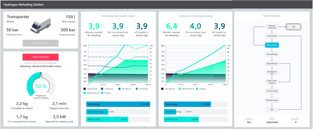
The model comes with a sketch animation that can be used to visualize the dynamic pressure and temperature evolutions in the different parts of the system on the sketch. Preconfigured plots and dashboards also help to better analyze and understand simulation results.
Example of simulation results
Thanks to this mechatronic model, simulations can be performed to capture the physical behavior of the different subsystems. We can for instance use it to, in less than 10 seconds of simulation time:
- Evaluate the time it takes to refill a tank depending on the initial pressure, the target pressure, the tank’s volume, the control strategy…
- Evaluate in each part of the system pressures, flows, and temperatures
- Size the thermal management systems to remove the right quantity of heat and keep delivering hydrogen to the vehicle tank in the right range of temperature
- Evaluate the energy consumed to compress hydrogen
- Size pipes and valves
- Validate and optimize control strategies
Connection of the system model to the PLC controller for control design and pre-commissioning
Then, the Simcenter Amesim standalone model that has been used for system design can also help to validate the PLC controls virtually and for virtual pre-commissioning. The controls are just removed from the physical system and replaced by an interface block, making it possible to connect inputs (control requests) and outputs (sensor measurements) to the PLC. The PLC can be real hardware or a virtual PC.
Finally, it is possible to launch the simulation from a friendly user interface that can also be used to visualize the dynamic behavior of the system with plots and animations. That’s also possible from the same interface to modify manually the operating conditions of the system, such as vehicle tank initial and target pressure, and the vehicle tank volume. The control strategies parameters can also be tuned to evaluate different strategies and improve control calibrations and system performances.
Conclusions
System simulation is a tool that can really help address hydrogen challenges. First, Simcenter Simulation makes it possible to design better systems on the first attempt. Many scenarios, configurations, architectures, and subsystem sizing can be evaluated virtually, quickly, and at an early stage of the project. It reduces risks, development time, and costs.
System simulation can also be coupled with the system’s PLC controller to validate, optimize, and pre-calibrate virtual controls. Using a physical model of the system for pre-commissioning also helps to reduce risks during the start of the real system.
Last but not least, the physical model can be used during the system’s operation as a digital twin to better understand and analyze the behavior of the real system.
