Simcenter Nastran’s fastest way to simulate tension and compression of airframe skins: Tension-Only-Quad
Why Simcenter Nastran is used to model airframes
Airframe structures must undergo a rigorous evaluation process to become flight certified. Finite element software is a critical tool used in the process as it enables simulation of the airframe to predict stress and deflections for many flight conditions.
Linear finite element methods are most typically employed because of their efficiency of computation for a large number of load cases. Under linear behavior, structures have the same stiffness independent of how they are loaded. This is a generally valid assumption however, in airframes with thin skin, the linear behavior assumption may not be valid.
When the load on the airframe changes
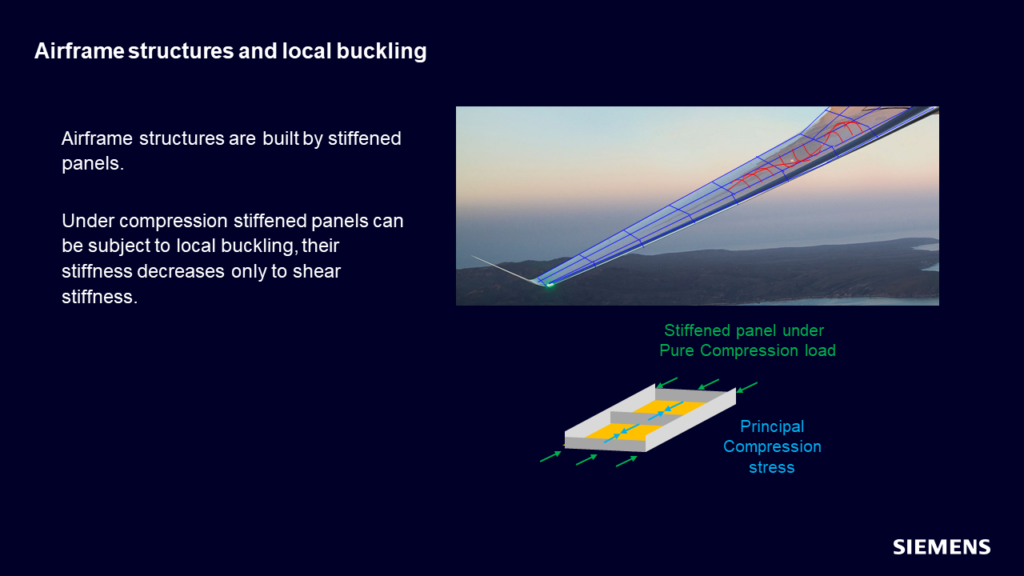
The skin structure not only provides the lifting surface but also supplements the load-carrying capacity of the spars, ribs, and stringers. The skin carries mostly membrane and shear loads. When the skin is in a tension-loading condition, it can carry both membrane and shear loads. But if in compression, depending on the framing, it can locally buckle. In such cases, it can no longer carry membrane loads but can still carry shear loads.
Existing modeling methods
In the past, airframe analysts have modeled this behavior using manual techniques. They start with a base model that uses standard shell elements to model the skin. In Simcenter Nastran, shell elements are modeled with CQUAD4 elements with the PSHELL physical property. This element type has both membrane and shear stiffness.
Then analysts perform a loads analysis to locate areas where the shell elements are in compression. In those areas where the compression level is significant enough, the analyst would create a new model by replacing the compressed shell elements with elements that only carry a shear load. In Simcenter Nastran, this is the CSHEAR element with the PSHEAR property.
As can be imagined, this is a tedious effort and requires creating multiple models corresponding to various load conditions. In addition, it becomes difficult to manage the models which makes certification more challenging.
The New modeling method
A recent enhancement has been made to Simcenter Nastran Multistep Nonlinear (SOL 401) to simplify the workflow for this use case. A new element formulation has been added that changes the stiffness characteristics of the shell element based on whether it is in tension or compression. Thus, only one model is needed for all the various load conditions.
In the new workflow, users again use a base model with shell elements. But the shell elements reference a new type of physical property called a shell/shear panel using the PSHLPNL physical property. The new property type has definitions for both membrane and shear stiffness properties. This new formulation is sometimes referred to as a tension-only quad element because it carries no compressive loads.
How the new solution works
The Simcenter Nastran Multistep Nonlinear (SOL 401), as the name implies, is a nonlinear solver and iterates on the stiffness until the residual forces are eliminated. Initially, the solution starts with the shell/shear panel elements with shell stiffness behavior. During the iteration process, the solver will check the internal loads in the shell/shear panel elements and the ones that have compression are converted to the pure shear formulation.
Converged solutions are typically achieved within a few iterations, so solution times do not take much longer than a linear solution. Additionally, users can solve many load conditions in just one solution.
The set-up
Users have several settings to consider when defining the properties of the shell/shear panel element. The properties for the shell and shear behavior are the same as for standard shell and shear elements. While the new settings control conversion from shell to shear. There are two main settings in this regard:
- Stress direction for conversion
- Stress level for conversion
For the shell/shear panel the user needs to define the stress direction that will be used to determine whether the element is in tension or compression. Options include the element X or Y direction, material X or Y direction, or the minimum principal stress direction. The software will compute the normal stress in this defined direction and is then compared to the user-defined conversion stress level. The default conversion level is 0.0, but it is often advised to use a small negative stress level instead.
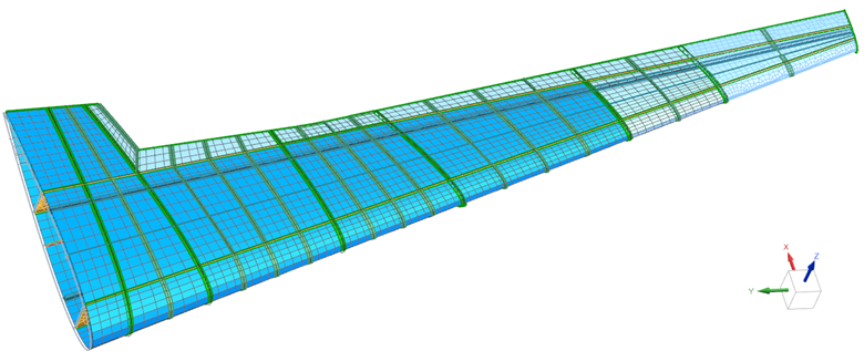
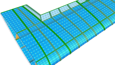
Figure 1 shows an example wing structure that is using the new shell/shear panel elements shown as the darker blue elements. The skin thickness in these areas varies from 1.2 mm to 2.0 mm. The stress direction aligned with the stringer orientation is used for the stress component to determine the conversion behavior. A material coordinate was applied to these elements to define the desired direction.
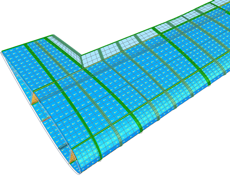
Figure 2 shows the material coordinate system assigned to the shell/shear panel elements. The arrows are showing the X direction of the material coordinate system which is the direction chosen for the stress evaluation. The stress level for conversion was set to -6 MPa for the thinner skin section to -10 MPa for the thicker section.
For the analysis, the wing is fixed where it would attach to the fuselage. A set of five force loadings were applied along the wingspan corresponding to various flight conditions.
Results
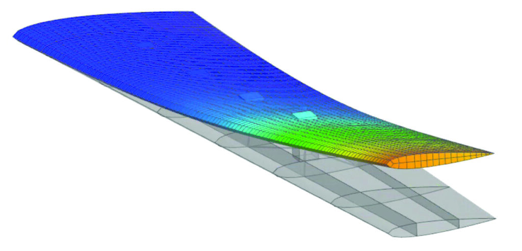
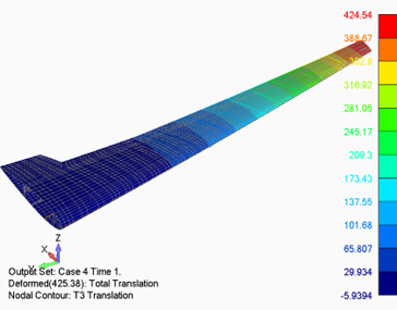
Figure 3 shows the deflection (in units of mm) from two of the load cases. Case 3, on the left, shows a downward deflection, and Case 4, on the right, shows an upward deflection.

One of the new results with the shell/shear panel elements is a status value. A value of 0.0 indicates that the element has not converted to shear behavior and a value of 1.0 indicates it has been converted. It is noted that each load case is solved independently and starts from an unconverted condition.
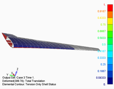
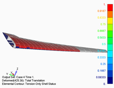
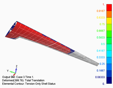
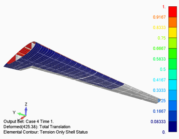
In load Case 3, where the wing deflects downward, the skin elements on the bottom of the wing are in compression and hence can be seen to have been converted. In load Case 4, where the wing deflects upward, the opposite occurs and the skin elements on the top of the wing are in compression and are converted.
Stress results on the shell/shear panel elements can also be displayed. Figure 5 shows the normal stress in the material X coordinate system. For elements that have converted, there is no longer any normal stress and subsequently, there are no results on these elements. For the unconverted elements, the normal stresses are seen in tension.
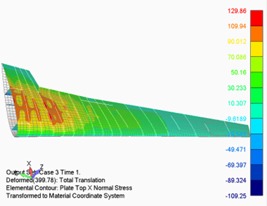
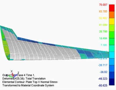
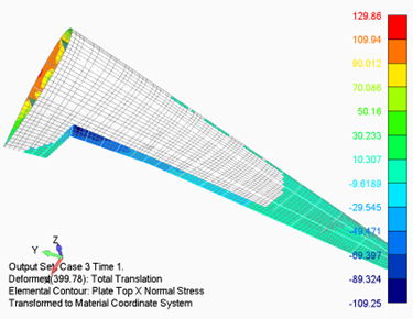
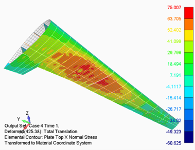
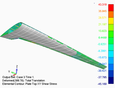
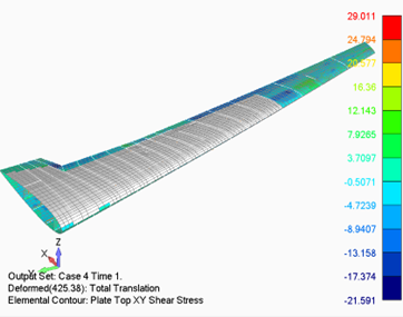
Figure 6 and 7 shows the shear stresses for the same load cases. The contours in Figure 6 show the shear stresses in the converted shell/shear panel elements. Again, for load case 3, the contours are only on the bottom side of the wing where conversion occurred, and for load case 4, the contours are on the top side of the wing.
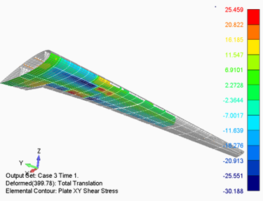
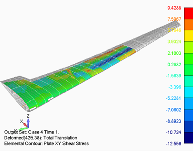
on top of the converted shell/shear panels
The contours in Figure 7 show the shear stresses on all unconverted elements and the standard shell elements.
Summary
Overall, the simulation workflow for airframe structures is significantly improved with the new shell/shear panel formulation and will lead to greatly reduced product development time.
Simcenter Mechanical
Simcenter Nastran is part of a wider group of products that provide mechanical solutions. From December 2022 these products aligned their release cycles, some of the highlights from that release are discussed in this blog, along with this Youtube Premiere


