Let’s get traction with 100s inverter designs and 1 well-integrated engineering workflow!
The engineering workflow, a methodology to succeed
In this blog post we’ll investigate an efficient way to design traction inverters. The integration of CAD and CAE models, as well as the transfer of parameters and reduced-order models all across the analysis, is leveraged to de-risk the engineering and reduce the development time.
The ultimate goal is to capture efficiently the interplay between distinct yet coupled physical time scales, physical and design length scales and how to bring down overall engineering time, optimize computation time and leveraging a high degree of automation.
Let’s gain design insights and reach more advanced performance predictions for the product reliability and vehicle integration. What an awesome plan for such a hot topic!
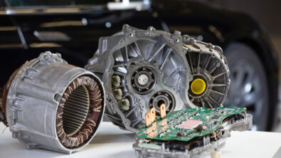
The automotive transformation to electric drivetrain is now
To reduce complexity and cost, and to optimize space utilization and weight, E-Powertrain systems and architectures are integrating and packaging together an increasing number of functions. This reinforces the need to design previously separated systems, components, and functions in a more integrated way and to manage the complexity of their increasingly tightly coupled interactions. This is the integrated design.
A full-vehicle system model is used to cascade the target vehicle performance down to component requirements for the electric drive and the inverter.
A pre-sizing analysis allows the down selection of the suitable components (SiC Mosfet, capacitors of the DC link, bus bars) and the validation of critical geometrical and design parameters.
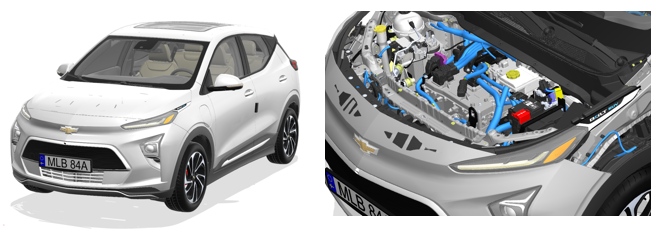
The design envelope and packaging space is provided by the Chevy Bolt dataset CAD model. The power modules PI2000 and PI4000 are authored by Siemens. The PI4000 is fitted with the suitable SiC Mosfet component and a 3D model of the inverter is created and designed in an integrated way.
From pre-sizing to detailed pre-design models
The design space defining the volume we can use for the traction inverter design is taken from a comprehensive Chevy Bolt CAD model dataset. A full vehicle model is created to provide boundary conditions to the traction inverter and component models created during the workflows. We also consider the DC link and the bus bar.

The pre-sizing model informs the selection of a suitable SiC Mosfet component for the PI4000 power module under maximum power scenario.
The level of fidelity of the traction inverter system model increases as the project transitions from pre-sizing to pre-design stage, where the DC link, bus bar and SiC Mosfet pre-sizing models are combined.
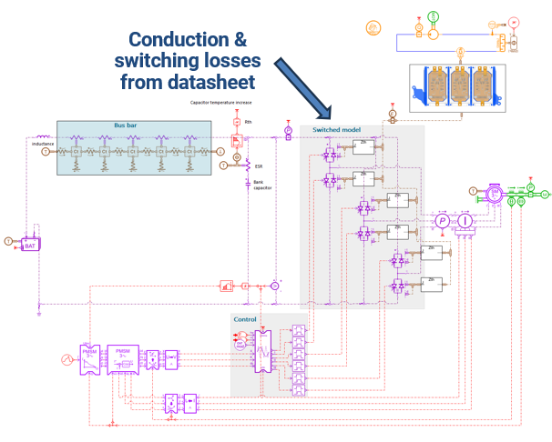
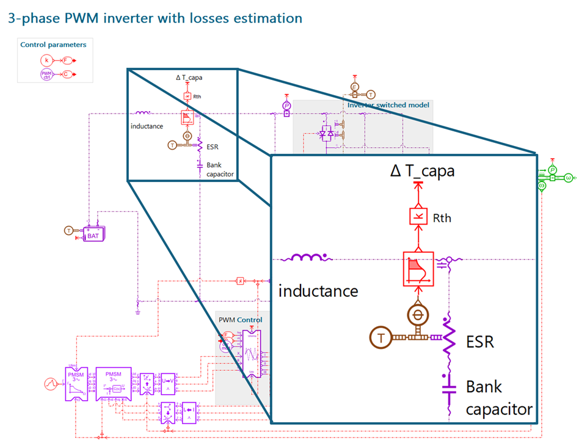
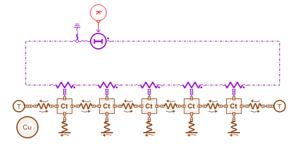
As we take advantage of these geometric parameter and functional system models we can already predict bus bar ohmic heating, DC link capacitor heat losses, conduction and switching losses in the SiC Mosfet and therefore the temperature evolutions of the major components of the assembly. We can arbitrate the effect of the cooling architecture layout on the temperature distribution between these components which is known to impact their performance and reliability.
Power module geometric integration
A CAD model assembling the various components is created. Based on the pre-sizing of the system and the associated component selection, we start with volume allocation and address the possible interferences between the selected components and the assembly. The DC link component is designed.

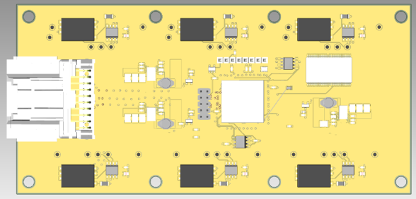
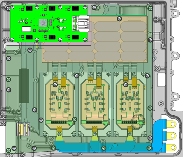
The 3 power modules of this 3-phases traction inverter are packaged together with a cooling plate connected to the cooling circuit. The circuitry of the PI4000 power module and INV100 Gate Driver are designed with the Siemens EDA solutions.
All these components are connected to the bus bars, which are molded with their filters. We finally define the final mechanical assembly of all the key power electronics components of the traction inverter design in the resulting CAD model.
At any point in the design process, the assembly components or the full CAD model can be run by the user through a simulation template to apply the preset fluid (for coolant in the cooling circuit and ambient air in the enclosure) and thermal boundary conditions on the new components. The electrical boundary conditions allows for 3D computations of the ohmic losses.
With this approach the thermal loads and boundary conditions are predicted under representative power and electrical loads. They can be used as input for the thermo-mechanical analysis.
When the component designs and their integration satisfy all the design rules and requirement the design of the traction inverter is frozen and committed to the next design stage. A thorough and systematic evaluation of the system performances is then performed against a wide array of realistic scenarios.
Results for the full energy balance vehicle
The powertrain system model is integrated into a full energy balance vehicle system model. Such a model is composed of a cooling and refrigerant circuit, a cabin model and a high voltage battery. It can account operations within different environmental conditions (temperature, altitude, solar load) and drive cycles.
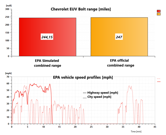
The powertrain efficiency is validated by comparing the predicted range with official EPA cycles. The model predicts a consolidated range of 244 miles versus 247 miles in official data.
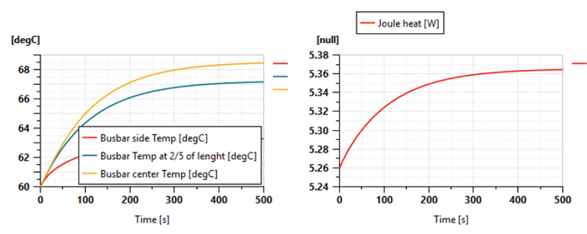
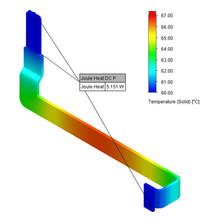
The DC bus bar cross section is determined at the max current operating condition with the objective to remain as light as possible and with a temperature increase lower than 10°C. After several iterations we select a Copper material with a 23x3mm section: the thermal response satisfies the design rules.

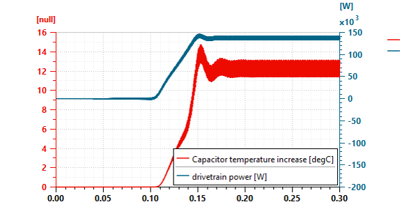
The DC capacitor is also sized in max power condition. The requirement of voltage ripples lower than 20V lead us to select a 1 mF DC capacitor.
Finally, we select the SiC power Mosfet and assess their thermal performance at the maximum power requirements.
Electrical, thermal, mechanical validation of the inverter design
Components are designed and integrated into the traction inverter assembly. The CAD engineer can directly apply preset automated templates to solve electro-thermal simulation and correct its design if design rules are not satisfied.
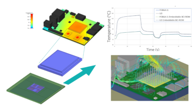
Once the full traction inverter mechanical design (CAD geometry) is in place, the thermal behavior of this system can be studied. This involves fluid flow, conduction and convection (conjugate heat transfer) and radiation. This integrated workflow provides detailed predictions by tightly coupling ECAD (electronics) and MCAD (mechanical) design systems.
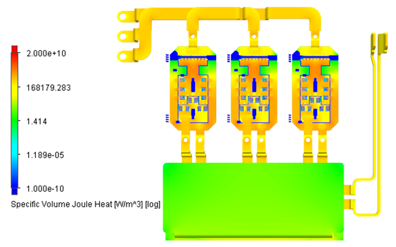
Within the formulation of this 3D simulation, the resulting system temperature levels are a combined effect of electronic component power dissipation, Joule heating and boundary conditions including the coolant temperature and flow rate, and the ambient conditions. Evaluating these temperature levels in various steady-state and transient load conditions serves to validate that all components remain within their specification for the operating conditions.

The dimensioning of the DC bus bars was determined at the pre-sizing stage; it is meaningful to verify in retrospect whether the 1D modelling approach resulted in reliable insight to dimension the eventual components and subsequently improve the fidelity of the system simulation. We observe that it is remarkably accurate.
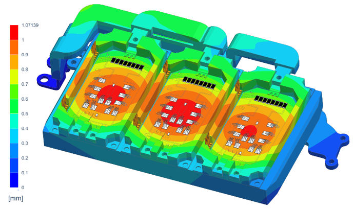
For mechanical integrity, the housing, cooling plate, power modules and bus bar assembly components were selected into a Finite Elements (FE) model. Components were meshed and material properties assigned. A simulation was defined to set up the structural analysis, to finally apply the spatial temperature results field output from the thermal analysis to get a temperature load in the structural analysis.
Integrated performance with fast CPU-time
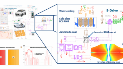
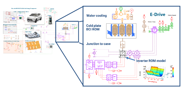
Let’s go to the final step for the integrated performance. The reduced quasi static model of the drivetrain and BCI-ROM of the combined power modules and cooling plate are integrated into a full vehicle energy management system simulation model. This model enables fast simulations compliant with typical vehicle long driving cycle scenarios and the evaluation of the vehicle performance, efficiency and thermal reliability based on diverse and realistic load cases.
As an illustration of systems models computational efficiency, such a detailed vehicle model is simulated over an FTP-75 transient cycle of 41 minutes in 5 minutes of CPU-time with a standard laptop computer.
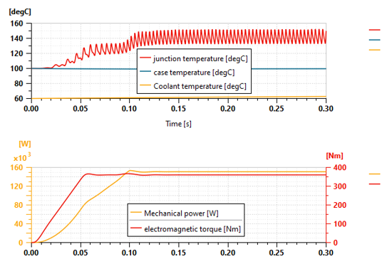
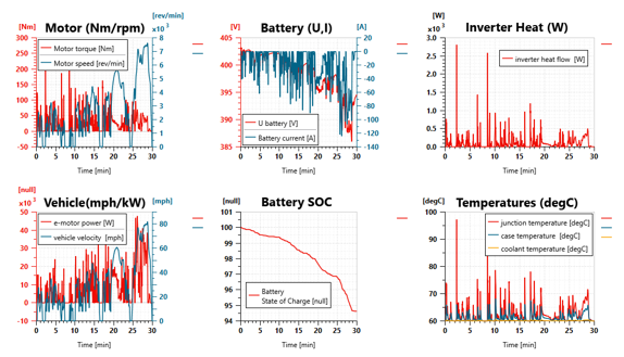
The powertrain was first tested on an abuse load scenario (full load, max speed with a 13% road constant slope and an ambient temperature of 35°C). The e-machine delivers an output power of about 100kW for half an hour, and the inverter junction temperature remains below 150°C.

Next, we tested the e-drive unit on a more conservative but dynamic WLTP scenario. In this scenario recurrent peak junction temperatures are observed on vehicle restarts phases which will require a careful design analysis.
That’s’ wonderful, everything works properly thanks to this easy-to-apply engineering workflow for the traction inverter design.
Takeways
Users can easily engineer a bespoke traction inverter with a 3D design fitting within the packaging space derived from the full-vehicle model. The engineering workflow leverages the seamless integration of the EDA, CAD and CAE models.
This robust approach facilitates complex analyses across electrical, thermal, and mechanical domains as well as functionally separated components. The integration of geometric and simulation models allows for persistent design validation as the design evolves. It’s key in a context where an increasing number of power electronics functions are packaged together and the power density and components temperatures are increasing.
Learn more about Siemens Simcenter Amesim
Simcenter Amesim is the leading integrated, scalable system simulation platform, allowing system simulation engineers to virtually assess and optimize the performance of mechatronic systems.