Enjoy every ride in any climate: your ultimate guide for thermal management in electric cars

The demand for electric transportation is increasing, and it’s crucial to manage battery pack temperature to enhance the safety, battery life, and driving range of electric vehicles. Additionally, passenger comfort should not be compromised, particularly in extreme weather conditions.
Studying and assessing design options for thermal management systems (TMS) is a complex task due to various parameters involved.
This study proposes a system-level modeling approach that includes:
- A complete electric vehicle model including the electric powertrain, the TMS, the vehicle, and the cabin.
- A functional and a physics-based representation of refrigeration loop system and chiller.
- A machine learning-based approach with neural networks to simplify detailed air conditioning system models for real-time control.
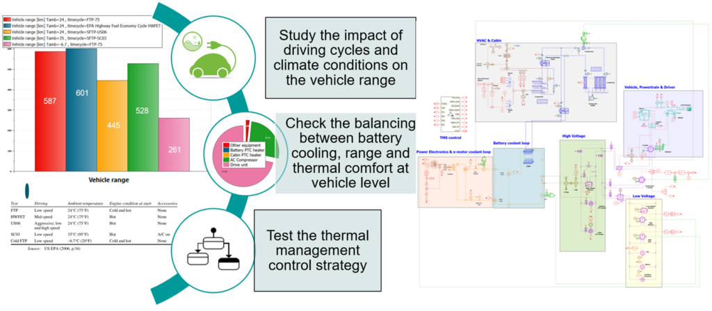
System simulation results using the proposed model over EPA 5-Cycles driving procedure are presented and analyzed. The impact of driving cycle and climate on energy consumption and driving range is discussed in detail, and modification of systems are proposed to obtain better energy efficiency.
Model development workflow
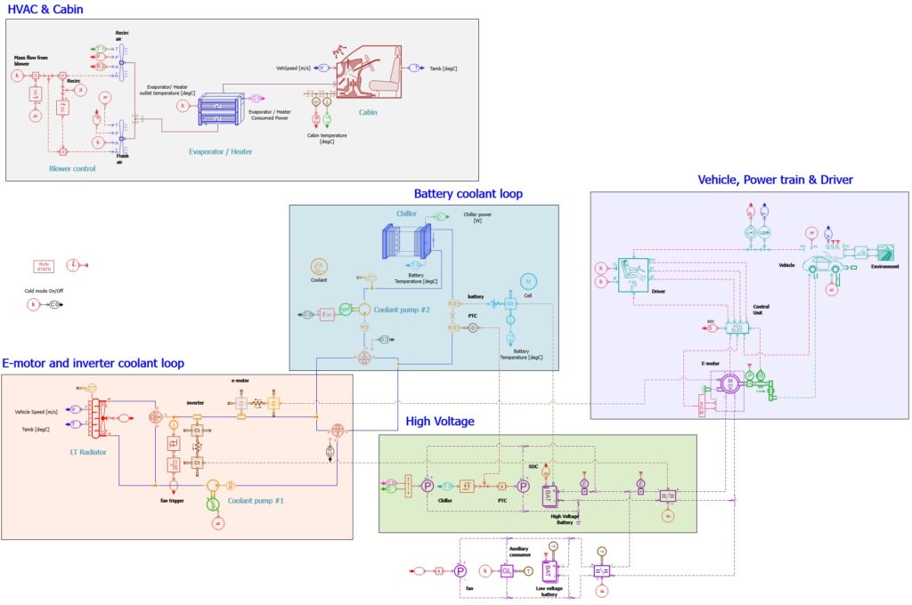
A model to measure the energy consumption of electric vehicles has been created using Simcenter Amesim. The model takes into account different driving conditions and environmental factors. It includes all energy losses from the battery to the wheels, as well as low-voltage consumers. The power consumption of thermal management circuits is estimated by modeling their performance.
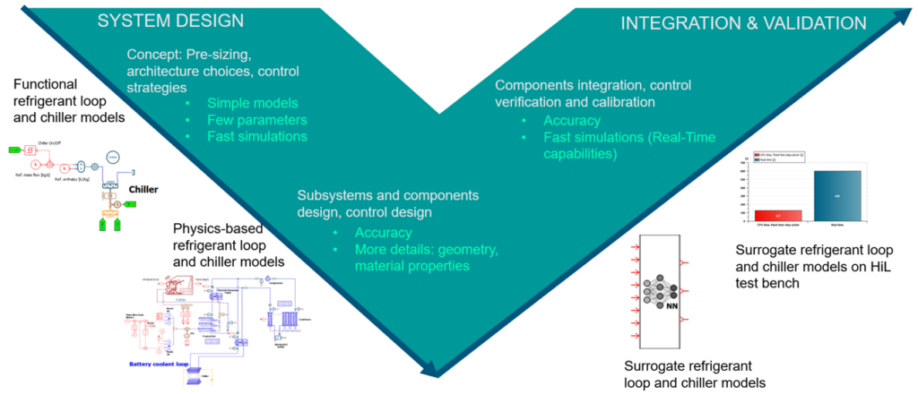
To consider the cooling and heating performance of thermal management systems and their power consumption, different levels of models are employed. A physics-based model of the liquid cooling loops is selected in all cases, while various modeling approaches are used for the refrigerant loop.
- First, a functional representation with Coefficient of Performance (COP) is used. A parametric study is performed for different values of COP to estimate its impact on the vehicle range
- Second, the refrigeration loop and the chiller are modeled with physics-based components to accurately predict thermal results
- Finally, the detailed air conditioning system model is reduced using a machine learning approach based on neural networks to ensure the model’s compatibility with real-time controllers and test platforms.
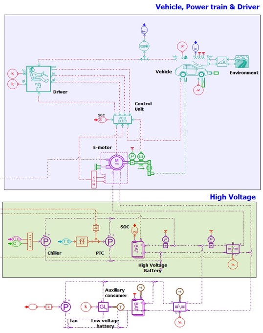
The electric powertrain model
The electric powertrain and vehicle models have been developed including:
- the motor and regenerative braking controller: it computes the requested motor torque to ensure acceleration. It also gives the needed braking command of the vehicle to follow the driving cycle.
- the chassis and environment: it is used to evaluate the car’s acceleration and velocity throughout the scenario. This velocity mainly depends on the electric machine torque, the resistive forces applied on the vehicle and the vehicle mass. Environmental temperature can also be set.
- the traction motor: the motor model gives the requested torque computed in the Vehicle Control Unit (VCU) to the powertrain. It computes realistic operating characteristics for a given motor considering its architecture and high-end performances (continuous power, maximum torque, and maximum speed).
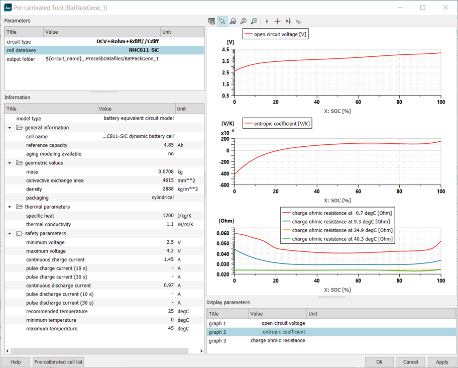
- a high-voltage electric bus with a high-voltage battery, an inverter and an e-motor but also the compressor for the HVAC system and the electric heaters. A dynamic equivalent circuit model of the battery cell is used to represent a high-power Li-ion NMC-C cell of 8 Ah. The model simulates both the electrical and thermal behavior of the cell.
- a low-voltage electric bus with a battery and consumers such as electric pumps, low-temperature cooling fan, and blowers
- the driver: it is used to predict the acceleration and braking commands to fulfill the driving scenario.
EPA 5-cycle procedure has been developed for conventional as well as hybrid vehicles. For Electric Vehicles, different adjustments are done to Derive FE label Estimates. The EPA uses five drive cycles performed on a dynamometer under controlled conditions to determine the fuel economy: a city cycle (FTP-75), a gentle [NB6] highway cycle (HWFET or HFEDS), an aggressive higher-speed cycle (US06), a hot-start with air conditioning cycle (SC03) and a cold-start cycle (cold FTP-75).
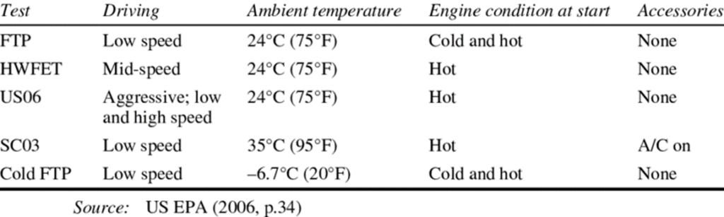
The two last cycles highlight the effect of temperature on the range of electric vehicles:
- Hot cycle: need to not only cool down the cabin but also the battery
- Cold cycle: no “free” heating coming from the ICE losses
The thermal management system model
Reference vehicle
The thermal management system of the 2019 Hyundai Kona Electric has been selected to create the simulation model.
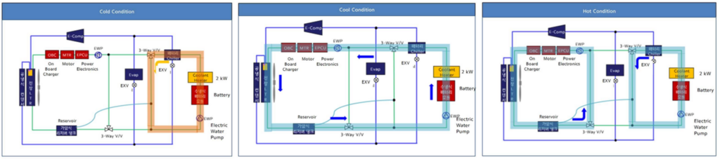
Three thermal management modes are employed for various temperature conditions:
- Cold conditions (below 0°C): Battery and cabin are heated using electric heaters. Coolant pump circulates fluid through battery and heater. Electric motor and inverter coolant circulation starts when they reach a threshold temperature.
- Cool conditions (between 0°C and 25°C): Heat from e-powertrain is released through the low-temperature radiator. Both battery and e-motor loops are connected, and both electric pumps operate.
- Hot conditions (higher than 25°C): Battery cooling is handled by a chiller. The motor and inverter are cooled via the low-temperature radiator. Cabin cooling is provided by an evaporator connected to the chiller’s refrigerant loop. E-compressor circulates refrigerant in the 2-phase loop.
Functional model of the refrigerant loop and chiller
In the initial stage, a functional model is used for the chiller and cabin evaporator, with a Coefficient of Performance (COP) imposed on it.
The chiller is activated by the battery temperature, and it removes 7 kW of heat from the coolant flowing through the battery pack. At the same time, the compressor’s electric power consumption is calculated using a constant COP.
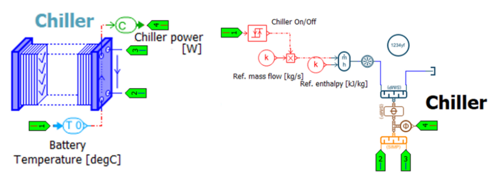
The cabin cooling evaporator generates up to 3 kW of cooling power to produce fresh air at 5°C. Electric consumption is calculated using a constant COP.
Initial results on the complete EPA 5-cycle procedure
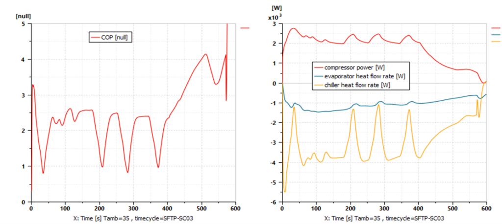
The first three cycles at 24°C do not need the compressor of the refrigerant loop or the PTCs. It’s worth noting that the range is lower on the SFTP-US06 cycle because it has a higher mean speed value compared to the HWFET and FTP-75 cycles.
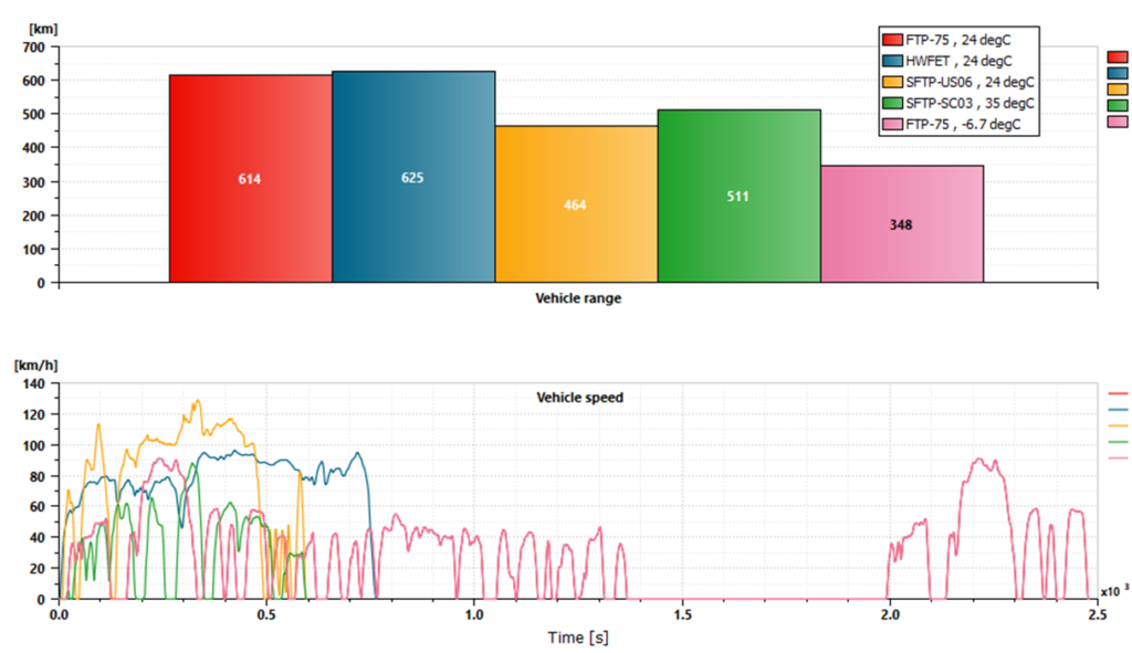
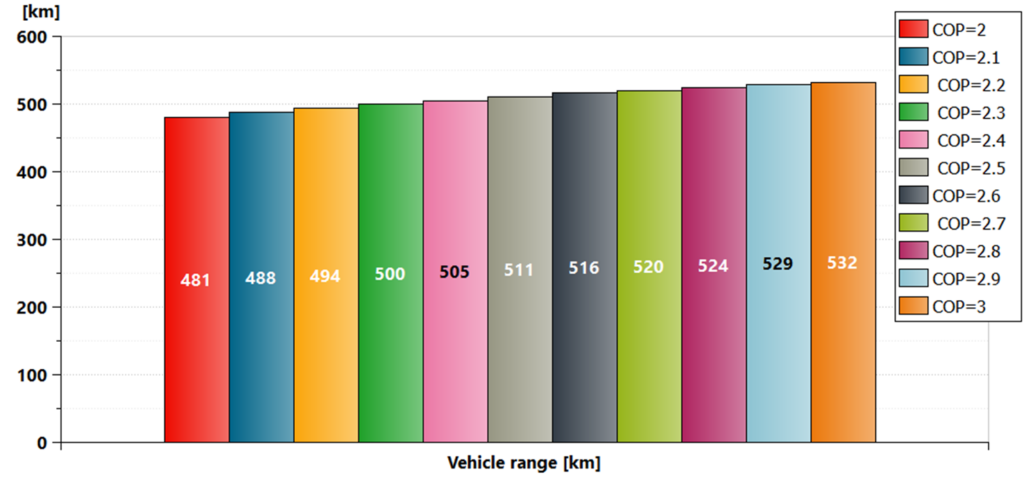
Let’s shift our focus to the SFTP-SC03 cycle which is performed at a temperature of 35°C. The simulated range for this cycle is around 511 km, and the refrigerant loop COP is around 2.5. The COP values of automotive air conditioning systems that operate with CO2 or R134a typically vary between 2 and 3, depending on factors like component design, compressor speed, and ambient temperature. Let’s run a parametric study to gauge the impact of COP on vehicle range estimation. Results indicate that an optimal refrigerant loop is essential for maintaining temperature control while minimizing consumption. The vehicle range varies from 481 km (COP=2) to 532 km (COP=3), which represents a difference of 11%.
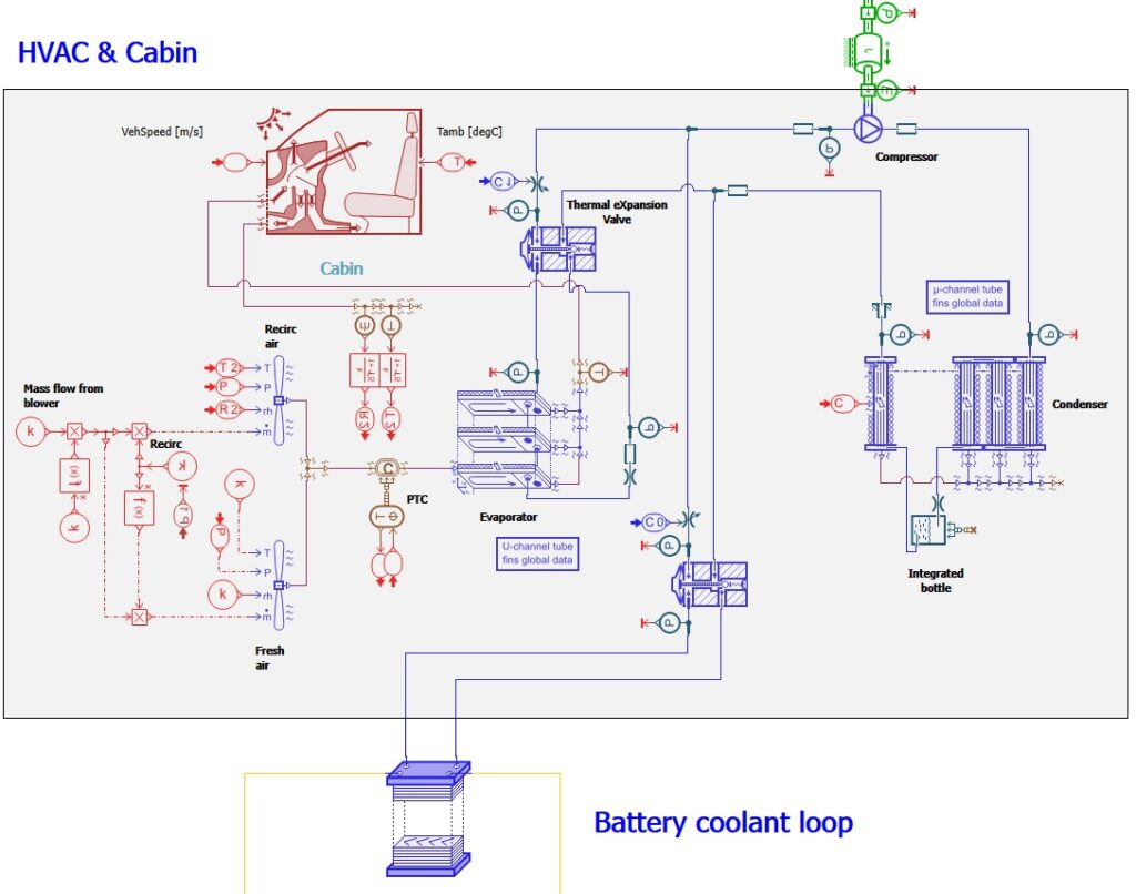
Physics-based model of the refrigerant loop
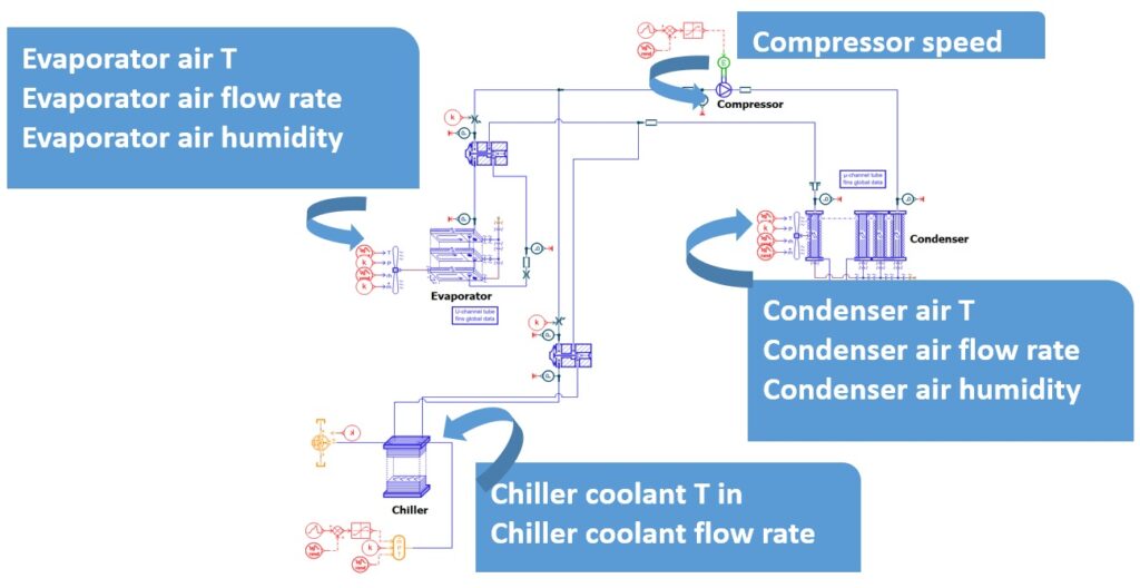
A new physics-based approach has been implemented to model the refrigeration loop system and the chiller. This approach is specifically designed for sizing air-conditioning components, particularly heat exchangers, and for performing transient analysis. It is based on basic elements such as boundary conditions, sensors, ducts, and pressure losses, as well as specific air-conditioning system global components like evaporator, condenser, chiller, and compressor.
To evaluate the maximum power of the chiller loop, a fast-charge simulation is conducted using the functional modeling approach. Following this, a physics-based model is developed based on the Simcenter Amesim Thermodynamic Cycle Tool. This tool is interactive and specially designed for sizing two-phase fluids based on thermodynamic cycles.
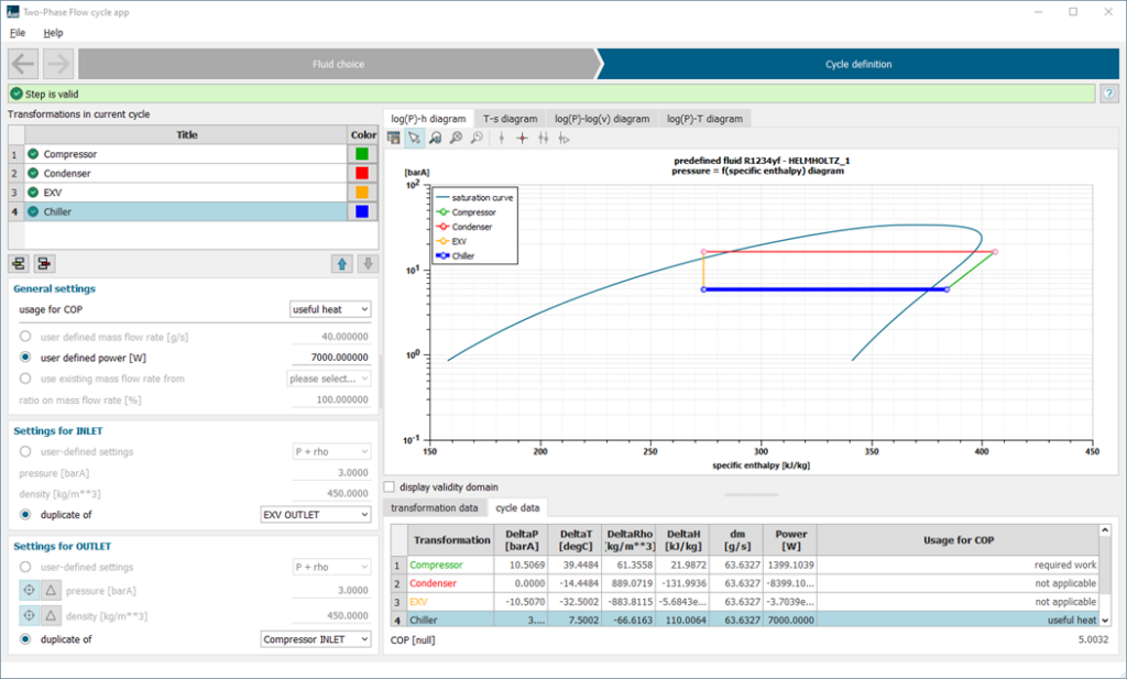
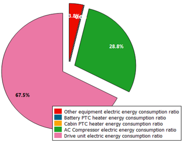
By adopting this approach, the coefficient of performance (COP) is no longer a fixed value, but rather a result of the refrigerant loop’s performance, which in turn is influenced by the sizing of its various components. When we simulate the SFTP-SC03 cycle at a temperature of 35°C, we can see that the energy consumed by the refrigerant loop accounts for nearly 29% of the total electrical energy consumption.
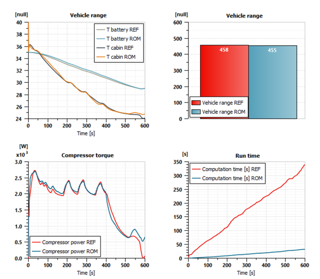
The use of this predictive method results in longer calculation times. With this physical approach, the CPU took 350 seconds to simulate 600 seconds, making it 1.6 times faster than real time. However, this is slower than the functional approach (which took only 30 seconds), making it roughly 14 times slower.
Surrogate model of the refrigerant loop
A surrogate model of the refrigeration loop and chiller has been created in order to perform real-time simulations.
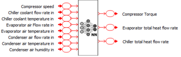
The models of the refrigeration loop and chiller have been isolated from other vehicle subsystems and controls. The aim of this is to create a virtual testing platform that uses a physics-based modeling approach to generate reference datasets. The corresponding results will be used to train and validate the surrogate model, which may also include test results. Initially, random values will be assigned to the 8 input parameters during a design of exploration computation in order to cover various operating conditions in a smart way.
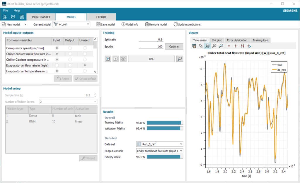
The model generates datasets that are utilized to train and validate the surrogate model, employing Simcenter Reduced Order Modeling. A range of reduced order models was executed to calculate a set of predefined configurations on the training data and perform an automatic exploration of models and hyperparameters. Subsequently, the best fidelity model (in this case, a dynamic neural network) was chosen and exported as a Simcenter Amesim submodel.
Surrogate model integration
The surrogate model is incorporated into the vehicle model by replacing the physics-based refrigeration loop and the chiller. When the ambient temperature is 35°C, simulation results for the SFTP-SC03 driving cycle are nearly identical to the physics-based model with the difference in vehicle range being less than 1%. However, the vehicle now runs 80 times faster than real-time.
Conclusion
This work presents a process for developing models, using various system simulation modeling techniques within Simcenter Amesim. The process is supported by Simcenter Reduced Order Modeling and is applied to an electric vehicle’s thermal management system. This methodology has been adopted by both industrial customers and universities, and those interested can refer to the following blogs or articles for more information:
- https://www.sae.org/publications/technical-papers/content/2018-37-0025/
- https://www.aachener-kolloquium.de/en/conference-documents/delayed-manuscripts/2022.html
- https://www.aachener-kolloquium.de/en/conference-documents/delayed-manuscripts/2022.html
- https://odr.chalmers.se/items/103d75bb-de0a-4dfc-a954-341d6b64a7ac
- https://aaltodoc.aalto.fi/server/api/core/bitstreams/42c9f01c-ab72-4470-82f2-462ff0d3826c/content
- https://doi.org/10.1063/5.0056364
- https://drpress.org/ojs/index.php/ajst/article/view/2932/2818
Learn more
Read this blog post to check out the latest release of Simcenter Amesim.
Discover our Simcenter portfolio of system simulation solutions on our website.


