Jet Engine Efficiency: Making Cleaner Skies the ‘New Normal’ Part II

Last week, I described how the current global pandemic provided one bright spot: the reduction in CO2 emissions. For such a reduction to persist when air travel resumes will require even further jet engine efficiency on the part of manufacturers.
Efficiency Requires A Multiphysics Approach
There are several factors in ensuring jet engine efficiency with a critical aspect being its thermo-mechanical performance. On April 16th I will be hosting a webinar (register here) discussing how we can help address the thermo-mechanical challenges for aero-engine manufacturers. We can summarize these challenges in three primary areas:
- Whole Engine Thermo-Mechanical Performance
- Whole Engine Vibration
- Component Structural Integrity & Lifing
Whole Engine Thermo-Mechanical Performance
Jet engines deal with complex physics by cleaning, compressing and streamlining free-flowing air. This, in turn, delivers highly pressurized and heated air into the combustion chamber to ensure a more efficient fuel burn. This pressurization and heat lead directly to both thermal and structural problems. But in reality, you can’t solve these problems separately instead this requires a multiphysics coupled thermo-structural solution; this is something Simcenter 3D’s multiphysics environment uniquely delivers.
Specialized Thermal & Structural Boundary Conditions in a Single Environment
Because of this unified environment, structural & thermal engineers can work on a single model across the whole engine.
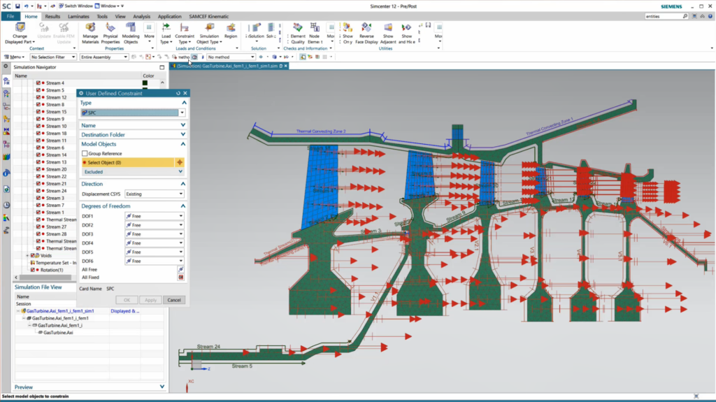
In the figure above, we can see a 2D axisymmetric representation of multiple stages of an engine with disks, blades, stators & housing. Using such a representation allows the engineers to quickly represent the 3D problem. Furthermore, in this model, the thermal boundary conditions have been applied and the user is in the process of adding the structural boundary conditions as well. Finally, the thermal BCs are specialized thermal streams to capture the heat transfer due to the fluid flow via 1D beams generated associatively from the CAD.
Multi-stage Cyclic Symmetry

Gas turbine engines comprise of a number of sections: broadly hot/cold sections (pre- and post-combustion) each with multiple stages. Each one of these stages having multiple sectors each with different sector counts; this can pose significant challenges as described in this previous blog post.
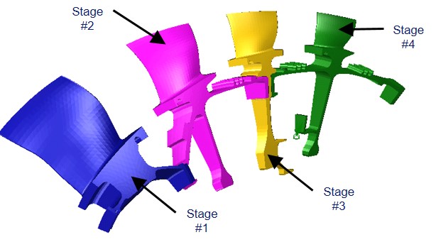
The solution is ensuring support for multi-stage cyclic symmetry conditions across the whole engine as shown above. Multi-stage cyclic symmetry is a unique feature of our rotor dynamics solution allowing us to model one sector of the rotating machine, but calculate it as a 3D model reproducing n times the initial sector.
Furthermore, Simcenter 3D offers an original methodology where it is possible to model sectors over multiple stages each with its own cyclic symmetry: for example, the first stage could have 120 sectors, the second 200 and a third 90 times. But Simcenter 3D can resolve across different sector counts and across different stages to innovatively analyze what would otherwise be a computationally-intensive solution.
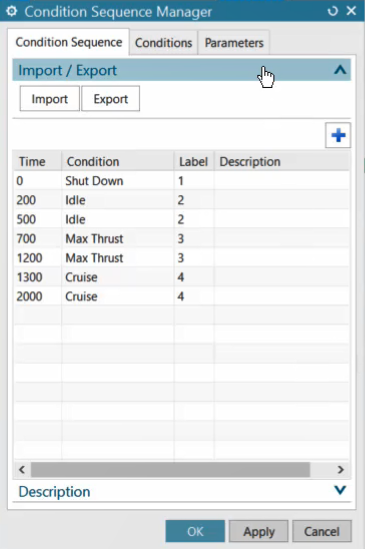
Condition Sequence Parameters Across Entire Mission Profile
Aero-engines do not perform one steady environment over the entire mission profile or flight path of the aircraft. For example, on a cold day, when the air density is high at ground level, the engine will produce higher thrust. On the other hand, on a hot day, or at high altitude, the situation will be reversed.
To simulate performance across multiple operating conditions would traditionally require multiple time-consuming simulation runs. However, using condition sequences, parameters can be input across the entire mission profile and solved in a single model.
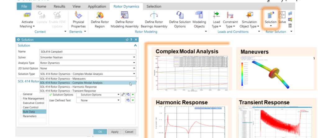
Whole Engine Vibration
For the engine to perform its primary function efficiently – delivering thrust – it needs to rotate vibration-free. Otherwise given the rotating speeds it is subject to, it could lead to catastrophic failure (see this excellent article by my colleague Sebastian for more in-depth details). These are speeds at which engines even with small imbalance can experience large and damaging vibration. Aero-engineers to use such simulations to make sure that the critical speeds are not close to desired engine operating speeds.
Simcenter 3D provides a new dedicated rotor dynamics solution that enables you to predict failure due to the critical speeds of the engine. This solution exists within the same integrated CAE Environment to address these problems.
Component Structural Integrity & Lifing
Realizing efficient blade shapes is key to getting the most efficiency out of aero-engines. It is sometimes said that gas turbine engineers mostly design the airflow through the engine and then have to design an engine to give that airflow. So aero-engine engineers start by designing the operating blade that gives the best efficiency.
The operating shape, however, can be significantly different than the manufacturing shape because operating temperatures and rotational loads cause deformations. Therefore engineers need methods to calculate the manufactured shape such that under operational loads, the blade deforms into the most efficient operating shape.
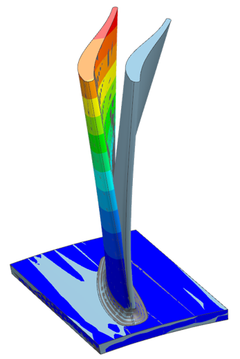
This is done by what is known as hot to cold analysis – hot being the operating shape and cold being the manufactured shape. Starting with the desired operating shape engineers can use Simcenter CFD simulations to predict the temperatures and pressures on the blade surfaces. Those loads can then be mapped to a structural model based on the operating geometry. Simcenter then has the capability to determine how the geometry needs to be modified or morphed such that the known applied loads will deform into the desired operational shape.
This results in the manufactured geometry configuration used to build the part and for performing subsequent service load simulations.
The gas turbine engine will not be going away anytime soon, but ensuring it operates as efficiently as possible will ensure our skies remain cleaner in the future.


Comments
Comments are closed.