How electrified aircraft propulsion impacts design processes
Aircraft propulsion is on the path of electrification. Initiatives are coming from all sides: start-ups, aerospace leaders and non-aerospace companies like Hyundai. Electrified aircraft propulsion is seen as an enabler of aviation environmental sustainability. Moreover, it’s a way to meet more and more stringent emission regulations. With these new powertrain designs, we can expect fuel consumption optimization, pollutant emission mitigation and noise level reduction.
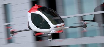
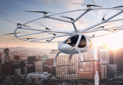
Using electric propulsion expands the design space. It allows for concepts built around several electric motors spread over the airframe. This is not possible with the conventional gas turbine due to its size. Moreover, it is easier to distribute power through cables than through shafts after all! Many concepts leverage this versatility to offer short or vertical take-off and landing (STOL or VTOL) capabilities. As an example of the emerging Urban Air Mobility (UAM) market, we can name the Uber elevate initiative, aiming to start operating an air taxi network around 2023.
Address systems complexity
These potential advantages come at the cost of an increased complexity. First, the integration of additional components, such as batteries and electric machines, requires additional expertise within the design team. This also implies an increased complexity on the controls side. In a hybrid concept, with multiple sources of energy onboard, the way you manage the split during the mission greatly impacts the aircraft performance.
On top of that, designers cannot rely on the experience from decades of development as they would do for more conventional designs! This lack of historical data also impacts the certification process (how would you translate the One Engine Inoperative (OEI) condition to the case of a hybrid architecture?). The authorities are reviewing their framework to be able to properly certify electrified propulsion systems. For instance, the EASA recently proposed means of compliance for electric VTOLs.
In this article, I will further discuss the impacts on simulation activities. Based on studies recently published together with Cranfield University [1][2][3], I will review new methods and tools that help design electrified aircraft propulsion.
Select the right concept
We have mentioned the freedom electrification offers in terms of propulsors layout. For a given set of operational capabilities, such as range, cruise speed or hovering time, several fundamentally different concepts might work. When it comes to selecting the right one, this additional freedom makes the job harder!
In [1] the authors show that the performance of the electrified powertrain can be assessed very early, using a model that simulates a complete mission. At this stage I feel the need to explain further what “early” and “simulates” mean in terms of tools and methods.
Sooner is better than later
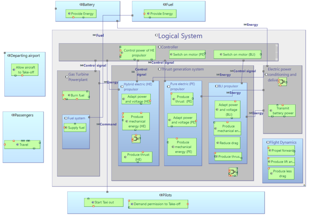
“Early” means we are still at a concept phase. Following the ARCADIA methodology [4], the authors have derived, from target operational capabilities, the logical architecture of a powertrain for a regional aircraft (ATR-42 type).
The only commitment so far is to look at a parallel architecture, where the propulsors are concurrently powered by the electric machines and the gas turbines. Designers have not committed to any component selection. For instance, the number of propulsors is not even decided yet. The architecture has not been optimized either, as the ratio of electrical power in the split is also left undecided.
Performance evaluation using system simulation
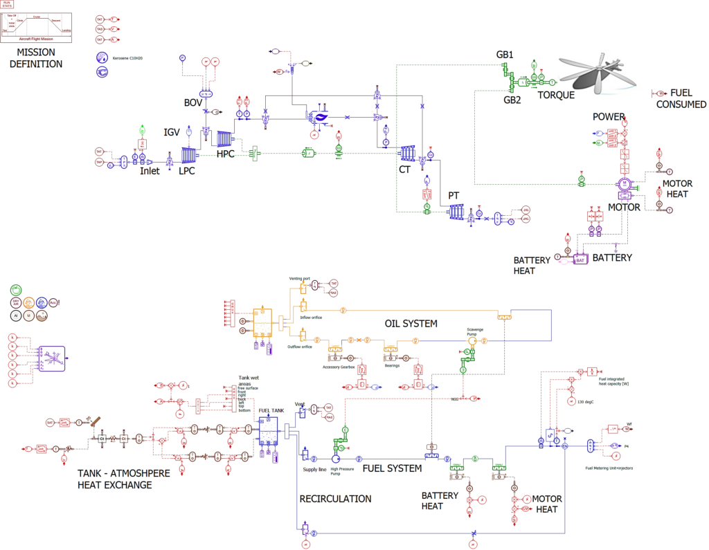
Here comes the value proposition of system simulation. From the logical architecture, the authors built a system model to simulate the powertrain performance over the entire aircraft mission. This is possible thanks to the database of the mathematical models available within Simcenter Amesim, addressing flight dynamics, electrical components, gas turbine, … among others. These models are combined in a graphical way. When few input parameters are available, the users can rely on existing templates and dedicated sizing tools (as illustrated by the gas turbine model generation tool, or the battery sizing tool).
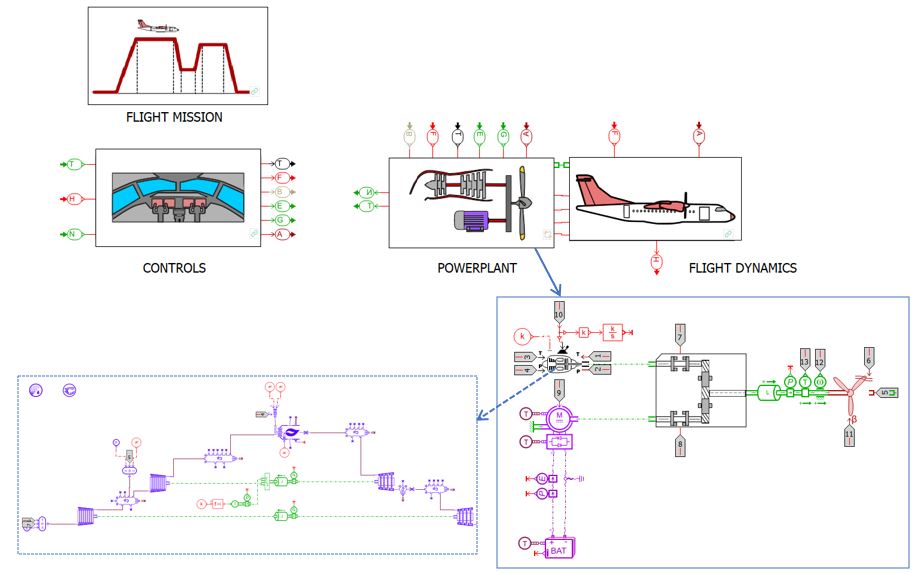
Note that this multi-physics system model is a dynamic one, allowing designers to look at transient effects. This feature is essential to look at the thermal behavior of the different components. And, spoiler alert, the thermal aspect is likely to be a breaking point for this type of architecture! But I will come back to that in the “Keep components cool” section.
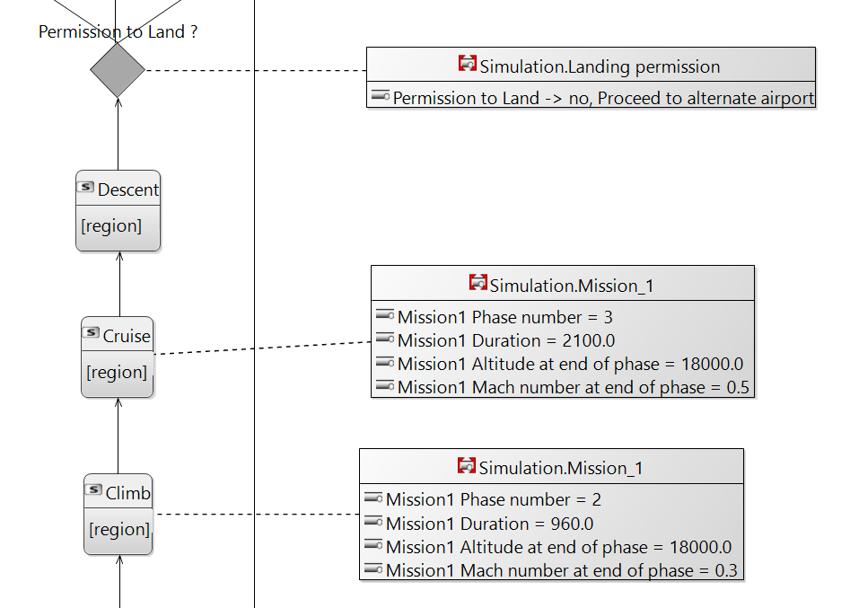
As you can imagine, a system description in Capella and a set of differential equations built within Simcenter Amesim are not made of the same material. To facilitate the transition, information specific to simulation execution were added to the Capella model, using the Property Values Management Tools:
Synergy between system architecting and system simulation
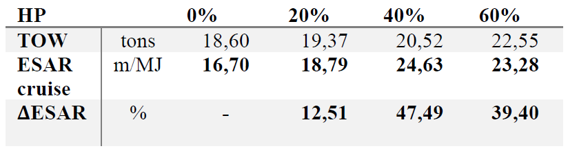
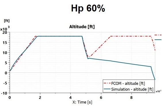
What conclusions did the authors draw from the simulation results? There are many, but one important take-away is about the ratio of electrical power in the split, the Degree of Hybridization (HP).
Remember that this Degree of Hybridization was left undecided in the logical architecture. The powertrain was then simulated with different values, ranging from 20 to 60%. The analysis shows that Energy Specific Air Range (ESAR), which is the distance covered per unit of energy, increases with the Degree of Hybridization up to a certain point. The best variant was found to be 40%. Above that, the added weight of the electrical components cancels out the benefits in ESAR.
Another important result is related to a certification requirement: the aircraft must be able to fly a reserve mission of 45 minutes solely on gas turbine power. The Simcenter Amesim simulations show that a Degree of Hybridization of 60% does not allow that and would require a different sizing method for the gas turbine.
Finally, the main take-away is maybe not these metrics, it is rather the synergy between system architecting and system simulation. Very early in your design process, a dynamic performance model can help you select the right concept.
Assess performance and pollutant emissions
Our societies demand faster transportation of people and goods, higher capacities and cleaner technologies. To accommodate these often contradictory targets, electrified aircraft propulsion is seen as a promising area.
This section discusses, based on the work done in [2], how simulation is used to assess CO2 and NOx emissions of a parallel rotorcraft hybrid electric propulsion system. The benefits of running simulations are two-fold. First, it is a way to assess how these emissions are impacted by design alternatives, such as different power management strategies. Second, it helps to look at other metrics, in addition to the emissions. It’s a good way to check that any improvement in terms of emission level is not made at the expense of operability for instance.
Impact of power management strategies on emissions
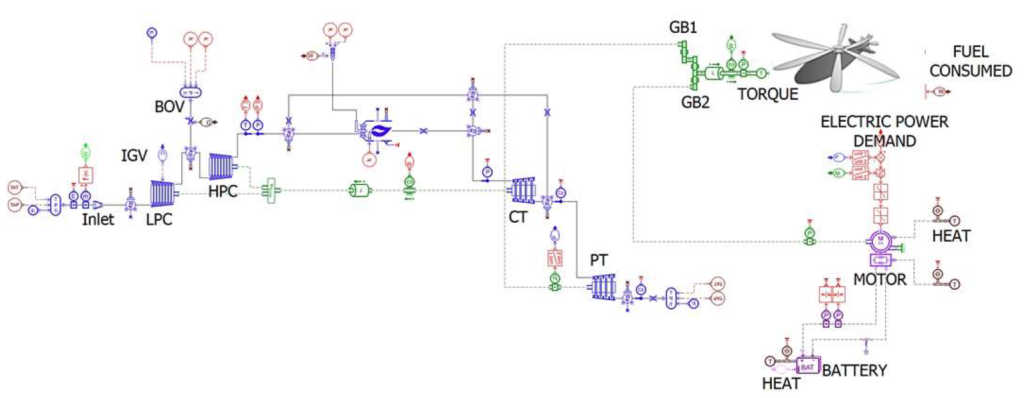
Developed with Simcenter Amesim, the simulation framework integrates the thermal and electric powerplant model, on top of a helicopter power demand model and suitable pollutant emissions calculation correlations.
Based on this model, the authors compared three power management strategies, leading to the following conclusions:
- Take-off and landing are fully electric. This strategy clearly offers benefits in near ground emissions, but not in terms of overall mission fuel consumption and pollutant emissions.
- The gas turbine is scaled down and electric power is used for high power request (“peak shaving” or “electric boosting” type of strategy). This one might offer reductions in block fuel and CO2 emissions. However, it forces the gas turbine to work at conditions that promote NOx formation.
- There is a power split between gas turbine and electric power. This version is more promising in terms of NOx reduction.
These conclusions are highly dependent on the technological level envisioned for the components (in the future we can expect better power-to-weight ratio for example). The results indicate that for current technology, hybridization is not expected to bring any benefits in terms of overall performance and emissions for the three power management strategies assessed. The reader is referred to [2] to get the full breadth of the study.
Trade-off with other attributes
The complexity of an electrified aircraft propulsion also lies in balancing multiple attributes. If the analysis presented in [2] is mainly about emissions, the system model gives access to other key metrics.
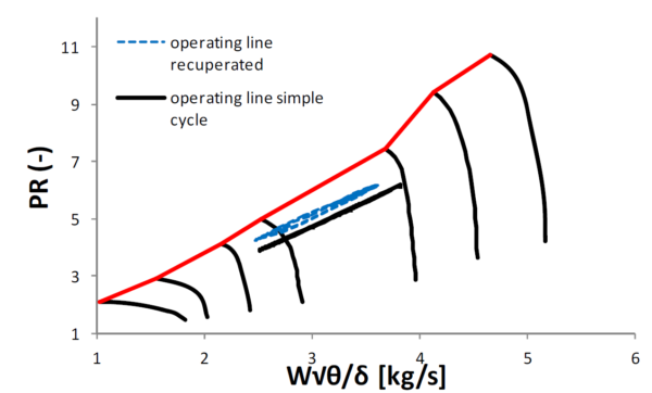
Operability is one aspect you want to keep an eye on as a designer. Changing the operating conditions of the gas turbine can lead for example to compressor surge margin reduction.
The powertrain weight should also be kept under close surveillance. Certain level of electrification can lead to an unacceptable payload carrying capability degradation.
Keep the components cool
Even if electrical components of the powertrain typically offer good efficiencies, the power levels lead to significant thermal loads. Designers must ensure that all components, from the fuel tanks to the battery packs, operate within acceptable temperature range during the entire flight.
I see one major challenge here. Static type analysis might not help at all with predicting a potential breaking point. Electrical and thermal phenomena have very different characteristic time. You may end up in a situation where the heat loading from take-off will affect the operation at some – hard to predict – moment in the mission. Even if the power request has been set to low values for a while.
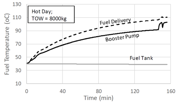
I guess you see where I am going with this: simulation can help! The idea here is to build a model that captures the dynamics of the different heat loads and heat sinks, on top of the propulsion model itself. The authors of [3] did that on a hybrid-electric rotorcraft case. The objective was to evaluate the viability of using the fuel onboard as a heat sink.
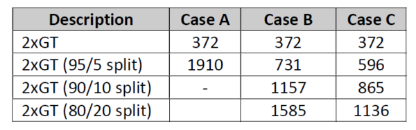
The authors run the analysis for different power management strategies, with or without fuel recirculation to enhance the system cooling capability. The study shows for instance that using only electric power for take-off would lead to very high fuel temperature, forcing the designers to consider additional heat sinks. When a power split is considered, the current thermal management system cannot cope with more than a 10% share of electric power in the split.
Conclusion
The three case studies share something in common: simulation helps tackling the challenges brought by electrified aircraft propulsion. All three cases – concept selection, emission assessment and thermal management – were addressed with a dynamic, multi-physics model of the complete powertrain.
Feel free to contact me at sylvain.pluchart@siemens.com or leave a comment below. I would be happy to exchange our experiences on these fascinating topics!
Related resources
- White paper: Achieving virtual integration of aircraft engine systems
- Blog post: Pre-sizing a hybrid-electric aircraft
- Blog post: Pre-sizing a turboshaft for an eVTOL in Simcenter Amesim
- On-demand webinar: Assessing thermo-electric powerplants for rotorcraft using system simulation
- Tech tips video: How to assess regional aircraft performance with Simcenter Amesim
References
[1] Roumeliotis I., Stavros V., Calum S., Broca, O, Cappuzzo F., “Application of Model-Based Systems Engineering for the Conceptual Design of a Hybrid-Electric ATR 42-500: from System Architecting to System Simulation”, ASME Turbo Expo 2020.
[2] Roumeliotis I., Arena F., Liu Y., Vouros S., Pachidis V., Broca O., Toure D., Unlu D., “Performance and Emission Assessment of Thermo-Electric Power Plant for Rotorcraft Propulsion”, ASME Turbo Expo 2020.
[3] Roumeliotis I., Castro L., Jafari S., Pachidis V., De Riberolles L., Broca O., Unlu D., “Integrated Systems Simulation for Assessing Fuel Thermal Management Capabilities for Hybrid-Electric Aircraft”, ASME Turbo Expo 2020.
[4] Voirin J.-L., “Model-based System and Architecture Engineering with the Arcadia Method”, 1st ed. ISTE Press, 2017.
[5] Roumeliotis I., Nikolaidis T., Pachidis V., Broca O., Unlu D., “Dynamic Simulation of a Rotorcraft Hybrid Engine in Simcenter Amesim”, 44th European Rotorcraft Forum, 2018.


Comments
Comments are closed.
Dear readers,
Some additional resource if you are interested in
– Battery pack modeling:
https://blogs.sw.siemens.com/simcenter/improve-battery-fast-charging-experience-while-limiting-battery-aging/
– The generation of reduced order models:
https://community.sw.siemens.com/s/article/Reduced-Order-Model-for-simulation-speed-up-with-Simcenter-Amesim-Version