Virtual Sensors accuracy improved by Test and Simulation

by Safak Has
Industrial trends
Automotive manufacturers are in a growing need to improve efficiency in their vehicle development process. This new challenge is a consequence of trends in the automotive industry, such as electrification, virtual sensors, new mobility needs, and other increased complexity.
Vehicle development teams need to execute performance evaluations on their new products to fulfill the expectation derived from the market. Traditionally, all performance evaluations were done through physical testing; today, it’s almost impossible to do this for every single design variant. The need for a virtual validation of the vehicle performance is increasing.
But this doesn’t mean that the need for physical testing is decreasing. Simulation models and simulated data still need to be correlated with real-life measurements to achieve realistic results. This approach shift from test-centric development to model-based development (MBD) provides better engineering insight by tightly integrating and balancing test and simulation to increase productivity in vehicle development.
Impacts to vehicle development teams
As explained above, the need for virtual validation is increasing. However, simulation engineers also need to validate their models by tuning model parameters and apply physical vehicle loads to their simulation model to increase realism. In the meantime, test engineers need to provide accurate measurements and be sure that they acquired physical data from all critical locations all around the vehicle.
It is also important to indicate that these two worlds are historically isolated from each other and exchanging data between them can be difficult. Important information might easily be lost when converting from one environment to the other.
Simcenter Model-based System Testing (MBST) is specifically aimed to bring simulation and testing into a single environment.
MBST can help:
- effectively visualize simulation models and loads cascaded to different components
- create accurate virtual sensors by optimizing model parameters
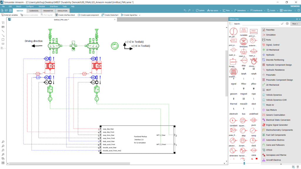
Visualize simulation models in testing software – Amesim sketch viewer
For complicated models, such as a full powertrain or complete vehicle, it’s very hard and time consuming to check the vehicle loads cascaded to every single component, apply specific load analysis, check the results, and compare the results in the simulation software.
To tackle this challenge, Simcenter Testlab enables the unique opportunity to open and visualize Amesim models directly in the testing software. This feature is called Amesim sketch viewer.
The Amesim data can directly be processed by Simcenter Testlab, which is specialized in handling large data sets and conducting load data analysis, in the exact same way as physical test data.
With this approach, test engineers can gain better understanding about the whole structure by accessing to the model easily. In the meantime, simulation engineers can benefit from proven load data analysis techniques which they can apply to a specific component from their model.
Create accurate virtual sensors using the FMI (Functional Mock-up Interface)
Next to processing simulation data in our testing environment, we can also simulate the model while feeding it with measured input data thanks to the functional mock-up interface (FMI) standard.
The FMI standard provides a possibility to import simulation models into Simcenter Testlab by converting them into a Functional Mockup Unit (FMU). This allows simulation engineers run simulation models and change model parameters directly from the Simcenter Testlab software. They can immediately see the impact of the change and compare the simulated data with measured data to better optimize simulation models.
From test engineer’s perspective, it’s not very easy to measure every single load from the vehicle. First of all, the limited resources constrain test engineers in the amount of sensors on a vehicle. And sometimes implementing a sensor might be hard due to the required effort to reach a specific location. There, we can use virtual sensor technology, where we can identify virtual sensors from a simulation model and obtain these quantities by applying real data as input. But we need to keep in mind that such simulation models should be accurate enough.
For this, we can correlate simulation and test data relying on model optimization as described above, since we can process and compare both simulation and test data based on the attribute we are focusing on, such as NVH, acoustics, durability, etc. Simcenter Testlab would be the answer to extend measured data sets with accurate virtual sensors relying on correlated simulation models.
Let’s see how all these are possible with a real-life application.
Application case – SimRod: Accurate virtual shock absorber forces
Imagine the case where we would need to obtain shock absorber forces from the electric car to use it as direct input for the FE-based analysis or physical lab test for durability and fatigue assessment. Putting a force cell to the shock absorber would be challenging, since a large load cell would change the structure around the shock absorber and can f.e. easily change the geometry of the sub-system.
It’s for sure that there is a relationship between shock absorber displacement and applied force. Displacement can easily be measures, but how can we accurately identify applied forces from these values? For instance, if we are focusing on durability, accuracy of force amplitudes are important and any variation might affect durability assessments. We can easily over-test or under-test the test object if we make mistakes when we try to estimate these input forces.
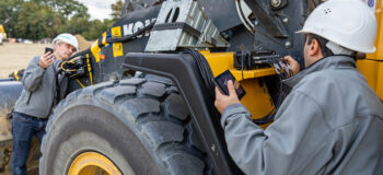
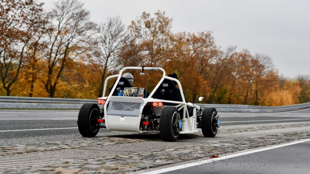
Some time ago, we have executed a data acquisition campaign with one of our electric vehicles on the proving ground in Aldenhoven, near Aachen in Germany. The vehicle we tested was a full electric sports car called SimRod (learn more about SimRod here). We use SimRod to better understand our customers and their need by carrying out test and simulation campaigns using the Simcenter test and simulation solutions.
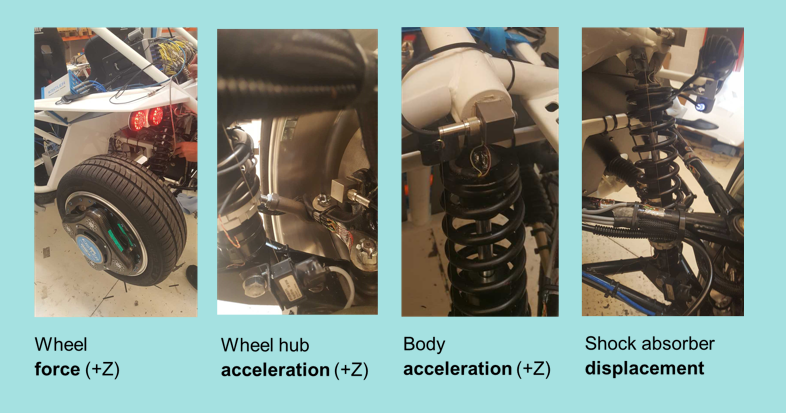
The data acquisition campaign took place on different road profiles and tracks, including Belgian blocks, Saw tooth and high-speed track. Below channels are extracted from this large data acquisition campaign and used for our application case:
- Wheel Force Transducers (WFT) force channels (z direction); Front and rear right
- Wheel hub acceleration channels (z direction); Front and rear right
- Body acceleration channels (z direction); Front and rear right
- Shock absorber displacement channels (z direction); Front and rear right
Aim of the study was to accurately extend the test measurement campaign with virtual sensors thanks to the MBST approach. In this context, subjected 1D simulation model (from Simcenter Amesim) is correlated (optimized) based on load data analysis which was conducted on measured data. After model correlation, new shock absorber virtual force sensors are created for both front right and rear right of the car. This enables simulation teams to execute FE-based analysis and test execution teams to perform component lab testing specifically on shock absorbers.
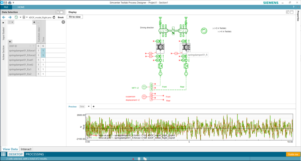
The functional mock-up unit (FMU) containing our Simcenter Amesim model is relying on a 4-degree-of-freedom system model which can be seen below.
Let’s step-by-step see how Simcenter Testlab can help us create accurate virtual shock absorber forces:
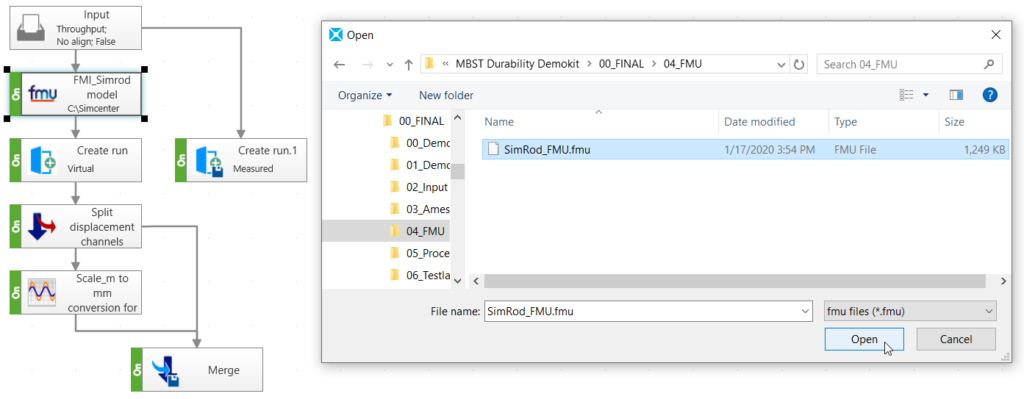
1. Apply real loads to the simulation model in testing software
We have imported the Amesim model into Simcenter Testlab as an FMU and have fed the model with measured wheel forces obtained by the WFT (wheel force transducers) inordered to get simulated outputs.
The output channels include the all 4 measured quantities described above and now include the virtual shock absorber forces which we couldn’t measure physically.
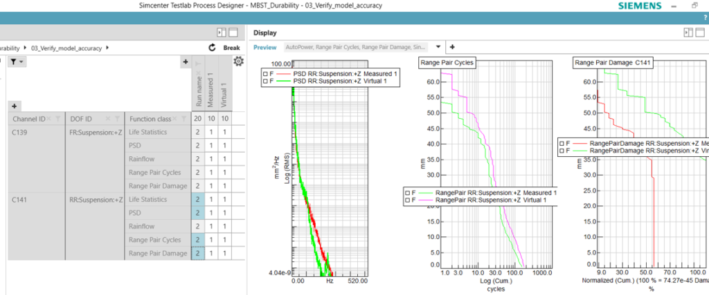
2. Verify model accuracy
Since we could measure the shock absorber displacements and get the same virtual output from the FMU containing the Amesim model, we’d use those 2 when we compare test and simulation.
If we check front suspension right side shock absorber displacement for both the measured and virtual channel, we would notice a very similar characteristic.
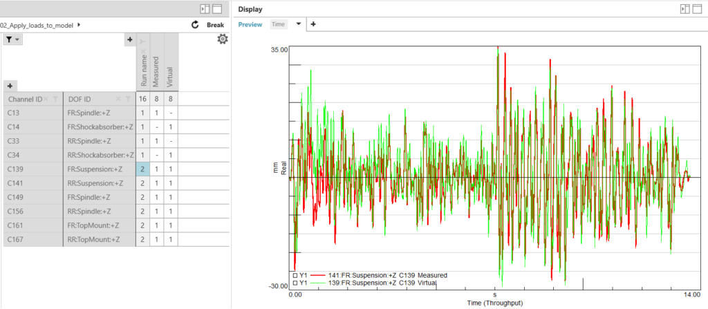
Is it sufficient to say we have similar fatigue potential? Well, not that easy…
Let’s further check by calculating Rainflow, Range Pair, Pseudo Damage and PSD (Power Spectral Density) on those displacement channels in order to compare damage potential between the measured and virtual data.
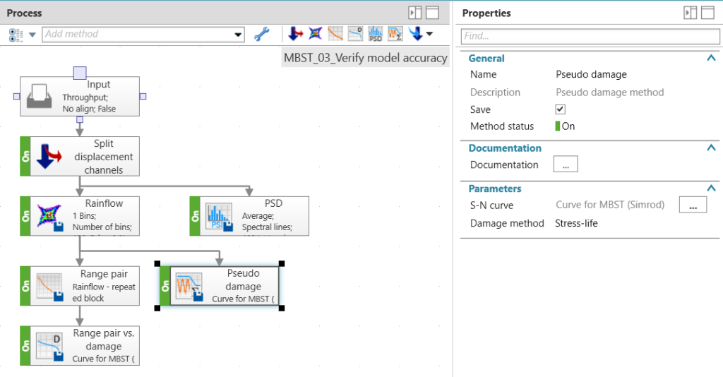
After we execute the analysis process, we see that the front suspension has similar results while the rear suspension shows quite large differences, since our virtual run has 1.73 times more damage potential compared to measured run.
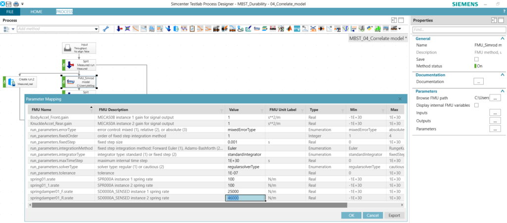
3. Correlate model and extend measurement with accurate virtual channels
Previous results give us the idea that we should change the model parameters and increase the damping characteristic of the virtual model to reduce damage potential.
After some iterations, we have increased the rear spring damping rate to a more accurate level. This can be done directly from Simcenter Testlab since our FMU still allows access to the Amesim model parameters.
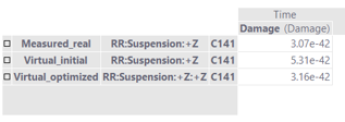
When the same analysis process is executed again on the measured and ‘optimized‘ virtual data, we see that pseudo damage values are almost the same (3.07e-42 vs 3.16e-42) for the rear suspension where the first virtual result was 1.73 times more damaging than the measured data (5.31e-42 vs 3.07e-42). It’s also worth to mention that we see very small damage values since this measurement was a short one obtained from the proving ground. In real life we see much higher damage values.
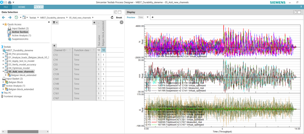
Since we have asked the virtual shock absorber forces as output from the simulation model, these are already obtained and correlated after we changed the rear spring damping rate. Now we can easily combine the measured data with the 2 correlated virtual shock absorber force channels (front and rear right) in a single run.
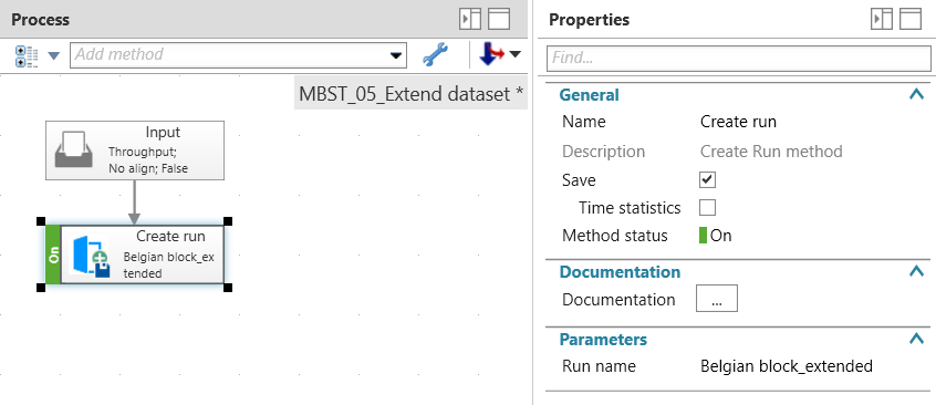
Here we have a single run with 10 channels that we can further use as an input for more durability evaluations.
With this nice application, we had the chance to go through:
- Visualizing simulation models – Amesim sketch viewer in Simcenter Testlab
- Model parametrization in Simcenter Testlab via FMI
- Virtual sensors creation in Simcenter Testlab via FMI
So, Simcenter Testlab helps with more insight, better models and optimized testing when combining Test and Simulation in one platform thanks to the model based system testing (MBST) approach.
As we can clearly notice, all these methods are used in a single software, Simcenter Testlab. We also use the same software for data acquisition and data processing across different testing needs like durability, NVH, acoustics, vibration control, etc.
Questions or curious about further capabilities of Simcenter Testlab software? Let us know. Just drop an e-mail at safak.has@siemens.com.
Learn more about Simcenter Model-based System Testing (MBST).