Clearances in gas turbines: the remarkable difference 1mm can make
I was thinking about clearances in gas turbines and I likened it to a close shave – you want it as smooth as possible but not so close that you actually cut yourself. Adopting the trend of utilizing ChatGPT I asked it for an analogy and I received the following: “A close shave is like walking a tightrope stretched over a canyon with the wind gently swaying the line. You make it across, but any misstep or wobble could have sent you plunging into the depths”. A little dramatic when it comes to shaving, but I must thank ChatGPT all the same as I think it reflects more the risks involved if uncontrolled rubbing occurs within a gas turbine. Now that would be a close shave!
The role of Whole Engine Model (WEM)
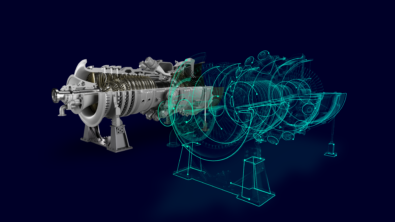
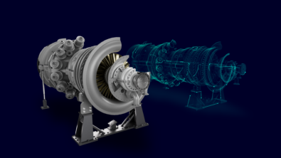
Predicting clearances in gas turbines is a complex and interdisciplinary task, involving transient thermal-mechanical modeling of all components within an assembly across various operational scenarios. This process, known as a Whole Engine Model (WEM), is crucial in the aero and power generation gas turbine industries. Understanding how clearances in gas turbines change over time is crucial for manufacturers. This knowledge allows them to optimize engine performance and efficiency while minimizing the risk of rubbing and other damage. The Whole Engine Model (WEM) isn’t just for assessing the steady-state condition of a gas turbine when it’s fully heated. It also helps analyze transient operations, where thermal gradients, temperature differences, and rotational loads significantly affect the gap between rotating and stationary parts.
Clearances in gas turbines: understanding metal expansion
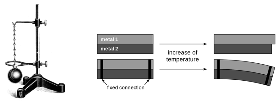
I’m sure most of you who remember your physics classes and the experiments with metal utilizing the ball and ring expansion and the bimetallic strip examples, figure 1. Metal expands when heated and different metals expand at different rates. In a gas turbine, and in particular heavy duty gas turbines, there is a lot of metal that is heated at different rates and amounts resulting in axial and radial expansion over the course of the operational cycle.
Impact of clearances on performance and efficiency
Gas Turbine OEMs are under tremendous pressure in a competitive market to deliver high performance and efficiency, both of which are intimately tied to the running clearances or gap between stationary and rotating parts. For example, 1mm of a clearance difference at turbine blade can have an impact of one megawatt (MW) which can power 650 houses in the United States (U.S.). That means a 500 MW gas turbine can power 325,000 homes, and just a 1 percent efficiency loss would mean powering 3,000 fewer homes. Alternatively, a study from Oak Ridge National Laboratory found that a 1 percent efficiency gain in a one-gigawatt (GW) power plant represents savings of 17,000 metric tons of carbon dioxide (CO2) per year, which is equivalent to taking over 3,500 internal combustion engine (ICE) vehicles off the road.
Therefore, the clearances in gas turbines need to be as small as possible to ensure maximum power and efficiency. In the context of a rotor with a diameter of 1 to 2 meters and a length between 5 and 15 meters, the 2D WEM enables simulating and illustrating millimeter-level displacements to optimize performance and ensure component integrity.
Evolution of the clearances in gas turbines
On top of that, the OEMs need to ensure that no structural damage occurs as the clearances in gas turbine evolve during the start-up and shut-down of the engine.
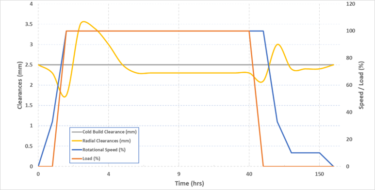
Figure 2 is an illustrative example of what happens to one blade as an engine speeds and powers up. The cold build clearance, or gap that is present once the engine is assembled and cold, is arbitrarily set here at 2.5mm. The gap changes and we see initially it closing to a local minimum at start-up due to the centrifugal deformation and little to no thermal load on the stator side. A maximum clearance subsequently occurs as the gas turbine increases its load and more heat is added to the engine. The stator, consisting of relatively thinner parts warms up faster but as the rotor increases in temperature, we see an evolvement to a steady state running clearance. At shut down the load is switched off and we see a closure of the gap further as the stator starts to cool down before the rotor. The gap opens once the load and speed drops, and we see a gradual return to the cold build clearances as the engine cools down.
Operational challenges and pinch points in gas turbines
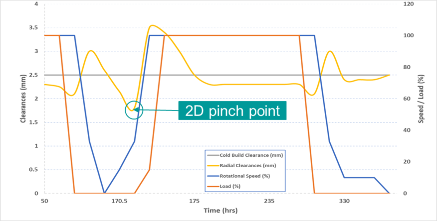
However, gas turbines have a wide range of operational scenarios, not just the idealized version representatively visualized in figure 2. Considering the current utilization of power plants as a back-up for green energy, the type’s of operation cycles the gas turbines have to endure are physically more demanding and characterized by frequent starts, stops and restarts. This has an influence not only on the lifetime of the parts, but also when and where local pinch points (tightest clearance or smallest gap) in a gas turbine occur. Figure 3 is an example of such a pinch point occurring at one blade location in the engine. One hour after shutdown, the engine is restarted and one can see how a new local minimum occurs as the rotor is still warm, the stator in comparison is cold and the centrifugal load is reapplied.
Leveraging Simcenter 3D for clearance analysis
Considering a typical industrial gas turbine, with approximately 15 compressor stages, and 4 turbine stages, the clearance engineer must carry out an analysis for each stage, and for all operational conditions, figure 4. This is where the WEM process within Simcenter 3D can significantly help the clearance analysis process. Reference points can be assigned within the model, for example, on the leading and trailing edges of the blades and vanes and the respective opposite locations on the stator and rotor. The transient results for the movement of these points can be read out from Simcenter 3D for further analysis in a tool like MS Excel or Matlab. This allows a clearance or mechanical engineer to build up a picture of the axisymmetric effects of the engine. Coupling these results to the non-axisysmmetric effects from other contributors (rotor-bending, casing deformation, etc), uncertainties and tolerances and the trusty engineer is able to build up a complete picture of the clearance behaviour of the gas turbine engine.
This type of analysis can be used by the project team to define and optimize the performance of the engine, minimize the rubbing risks, and define the safety margins to be employed. Other decisions like abradables, squealer tips and ultimately the final manufactured and assembled state can be made with confidence using this a priori knowledge of the clearance behaviour of the gas turbine engine.
If you want to unlock faster innovation, reduced risk and superior efficiency in your next turbomachinery project, we invite you to watch our on-demand webinar covering multidisciplinary analysis and optimization (MDAO) for gas turbines.