Simcenter FLOEFD: CFD for Design-Engineers – Part 3
This is Part 3 of a 4-part series explaining the technology behind Simcenter FLOEFD. Here we will discuss how these technologies allow Simcenter FLOEFD to solve complex fluid flow and heat transfer problems. Part 1 introduced some of the main technologies that make the above statement possible. Part 2 demonstrated that designers can easily use CFD for their tasks. Part 4 will demonstrate the enhanced turbulence modelling capability of Simcenter FLOEFD (links to the other posts provided at the end of of this article).
Using CFD to solve the complex heat transfer in a Nuclear Reactor for Thermo-structural analysis
Problem Statement
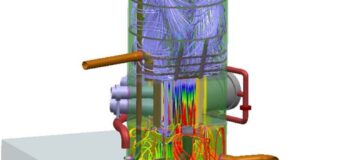
A fatigue-life assessment of a light water nuclear reactor vessel and supporting structure was required. The complexity of the system required a combined effort from the mechanical and nuclear engineering teams to provide an engineering solution to the problem. A brief description of the system is as follows. The entire vessel is submerged in a pool of water to absorb the nuclear radiation energy emanating from the core and passing through the solid structures. There are also two more fluid paths; 1) the main cooling flow entering the vessel at the top, passing through the reactor core and exiting at the bottom, along with 2) the blanket region cooling flow in the mid-section of the vessel around the core consisting of the main facility and test tubes. CFD is well suited for solving the cooling flow, however the nuclear radiation is not something that CFD is particularly capable of solving. Consequently, the nuclear radiation heat transfer rates were provided by the nuclear engineering team, and modeled by means of spatially dependent heat loads on the main components of interest.
Apart from the complex physics involved, the geometry itself is very complex. The entire vessel is littered with very intricate welds. These welds could not be ignored as they form areas of potential stress concentrations crucially important to the fatigue life predictions. There are also a host of small annular cooling flow passages (only a few millimetres wide) around the various test tubes and main facility tube. Within the core itself, the fuel elements and control rod elements combined consist of approximately 600 plates in total (±1mm thick, ±3mm spacing). Over and above that, these elements (along with all the other components in the core) are packed with very small spacing between them. Neglecting these spacing gaps for the sake of reducing the meshing overhead and simplifying the numerical solution was not an option. Doing so would reduce the open flow area and force the flow through the core at an unrealistic velocity, adversely affecting the heat transfer and pressure drop characteristics through the core. I think you’ll agree that this is indeed a complex heat transfer problem to solve with CFD…
Well, Simcenter FLOEFD was able to capture all the intricate small weld details, spacing gaps and cooling passages with ease, producing the first results within a few days. Yes, there was still a lot of CAD preparation work necessary to ensure contact between all necessary components and closing up any potential leaks, but there were virtually zero geometry simplifications made. The CAD preparation took up most of the time but was still very easy to do thanks to the combination of the synchronous technology in Siemens NX and the leak detection tool in Simcenter FLOEFD. It should be noted that the robust and stable mesher and solver also helped to identify leaks in the geometry by solving the flow through any small little gap that one may have missed. It just helps to get through the CAD preparations quickly and easily.
Results
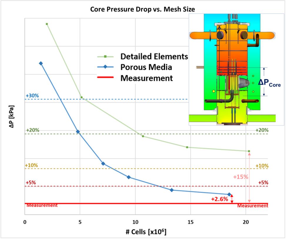
Initially the fuel plates were modeled explicitly, up to the point where the limits of computer memory prevented further refinement between the plates. At this point the total mesh size was already at 20.3 million cells, with the mesh resolution shown below. The core pressure drop predicted by the simulation was still 15% higher than the measurements. Ideally, to predict pressure drop across the plates more accurately, one would strive to obtain at least 4 cells between each plate. Interestingly though, the predicted temperature rise across the core was always within 3% of measurements regardless of the mesh resolution, from 2 million cells (yes for the entire vessel) up to 20 million cells – SmartCells™ very much at work here.
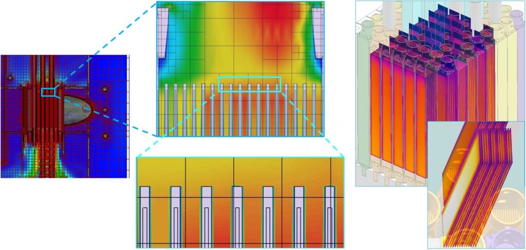
Out of necessity (with this being a nuclear application) to get more accurate core pressure drop results, the fuel plates were modeled as porous media, which were characterized for pressure drop and heat transfer. Only the stack of plates within the elements were represented by porous media, the element housing, inlet and outlet adapters were modeled explicitly, maintaining the small spacing gaps between the various elements. In this case Simcenter FLOEFD very easily predicted the pressure drop across the core to within 3% with ‘near as makes no difference’ the exact temperature rise of the cooling water across the reactor core (as it should be when using the porous media approach). The mesh dependence of the pressure drop across the core is shown below with a comparison between the two approaches, i.e. explicit versus porous media representation of the plates.
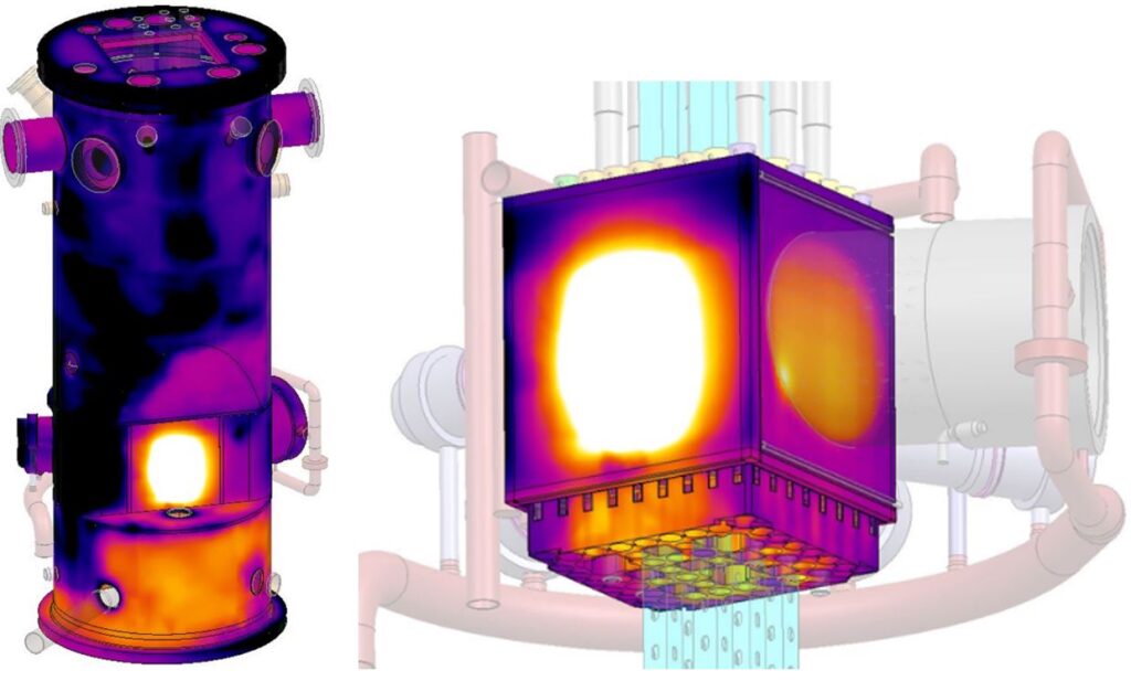
Once the CFD results were within acceptable levels of accuracy, the temperature and pressure distributions were successfully exported directly to the FEA input files, using the “Export Results” feature in Simcenter FLOEFD, for the subsequent structural analyses. A few examples of the resulting temperature distributions are shown below.
Conclusion
There is a lot more to say about the work presented here, but in summary it serves as a really good example of how the advanced technology in Simcenter FLOEFD is able to produce reliable results of complex heat transfer problems efficiently and within practical timescales.
Please continue to Part 4 where I shall demonstrate the accuracy and consistency of the enhanced turbulence model in Simcenter FLOEFD…
Part 1: The Technology behind CFD for design-engineers
Part 2: Design and optimization of a flue-gas stack (Example of Simcenter FLOEFD for Design)
Part 4: Benchmarking the enhanced turbulence model in Simcenter FLOEFD for automotive aerodynamics


