Simcenter FLOEFD: CFD for Design-Engineers – Part 1
This is a 4-part series explaining why and how Simcenter FLOEFD is the right CFD software for design-engineers. Part 1 will introduce some of the main technologies followed by a few examples in Parts 2, 3 & 4 of this series that aim to substantiate the above statement (links provided at the end of Part 1).
The Technology Behind CFD for Design-Engineers
Computational Fluid Dynamics (CFD) can be very difficult. Don’t get me wrong. I appreciate the pretty pictures that CFD deliver as much as the next guy. But it is a world full of physical and numerical complexities that pose quite a few challenges for the use of CFD by designers and engineers. Think CAD geometry imports, meshing, boundary layers, turbulence models, solver settings, convergence and computer resources…
Fortunately, there is a solution. Enter Simcenter FLOEFD…
Thanks to Simcenter FLOEFD, CFD for the design-engineer has become a reality. Simcenter FLOEFD is a design-centric CFD simulation software that consists of a host of advanced technologies that work together seamlessly to allow the application of CFD simulation upfront during the design phase of a product. In other words, it enables frontloading of CFD. Have a look at this white paper that explains in detail all of the technologies required to realize frontloading CFD. In this blog series I will just highlight some of the main technologies and demonstrate their practical implications.
It is the underlying technologies that make it possible for Simcenter FLOEFD to be used by Designer level users. They are then able to quickly, yet confidently, investigate trends during the early design phase of a product. Engineering level users can expand the use of Simcenter FLOEFD to consider the product within the larger ecosystem and constantly improve performance of products or systems based on more up to date information of the operating environment of the product. Simcenter FLOEFD also allows engineers to use CFD for their day-to-day engineering tasks, like root cause analyses for example. Analyst level users can also rest assured knowing that the Design and Engineering teams have produced reliable CFD results allowing the entire product development team to work together seamlessly for increased levels of productivity. Now, let’s discuss these technologies.
CAD Embedded
Simcenter FLOEFD is embedded in the most popular MCAD systems on the market namely Siemens NX, SolidEdge, CATIA and Creo. This allows the user to stay within a familiar environment and work directly on the CAD model during model setup (pre-processing) and analyzing the results (post-processing). That is not the full story however.
CAD embedded doesn’t mean just a nice ribbon or toolbar inside of your CAD interface, or simply a nifty tool to do quick and dirty CFD simulations for the sake of pretty pictures. No! In this case CAD embedded means directly connected to the CAD kernel, tapping into the background information describing the geometry and as a result being fully aware of geometric features like the radii of rounds, diameters of pipes or the distance between walls etc.
This is the key enabler of the SmartCellsTM technology – I will share more information about this later. Another added benefit of the CAD embedded nature is that there are no geometry translations to neutral CAD formats where errors easily and frequently creep in. For a good example of the CAD embedded nature of Simcenter FLOEFD, refer to Part 2 of this series.
Immersed Boundary Cut-Cell Cartesian Grid
CFD can get quite meshy. The user must choose which type of mesh to use based on the type of flow problem and geometry. Simcenter FLOEFD on the other hand consists of only one type of mesh. A Cartesian immersed boundary grid. This choice of grid was a conscious decision for the stability and robustness of the numerical solution.
In order to “facilitate” the use of a Cartesian grid, an innovative solution had to be devised for the wall treatment in the “cut-cells” (cells containing the solid-fluid boundary), see the 2-scale wall function discussion below. The added benefit of this grid choice is that meshing in Simcenter FLOEFD is a predictable, controllable and methodical process based on octree refinement, where one level of refinement divides a cell in half in all three dimensions resulting in 8 new cells (hence octree).
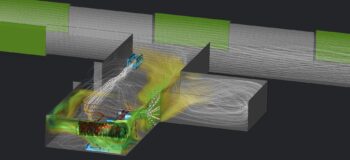
Mesh refinements can be driven by geometric features like vertices, edges, faces or volumes (based on physical components or virtual regions). The mesh can also be refined based on scale, such as small solid features or curvature, making it a truly flexible and economical way to refine the mesh where it matters. On top of that there is also the Solution Adaptive Refinement (SAR) approach in which the user can let the solver decide where to focus the mesh refinements to optimize the mesh within a limiting total number of cells. The best example to demonstrate that is of course with shock waves – See the animations below.
But the advantages don’t end there. Due to this robust meshing approach, Simcenter FLOEFD is very accommodating and tolerant of complex and even “dirty” CAD. By complex CAD I mean obviously any arbitrary complex shapes, but especially when there is a lot of small intricate geometric details or narrow channels involved. And by “dirty” CAD I mean poor definition of the geometry, for example small gashes or invisible surface impurities, resulting from poor exports into neutral formats etc. The robust meshing approach in Simcenter FLOEFD (in conjunction with SmartCells) minimizes the amount of CAD clean-up or preparation required to generate the mesh and run the first calculation, without any solver crashes I might add.
At this point I hope you don’t mind me stating that the absolute best marriage between CFD and CAD is Simcenter FLOEFD for NX. Siemens NX produces high quality CAD geometry that Simcenter FLOEFD can tap into. Siemens NX is also a fantastic CAD clean-up tool thanks to synchronous technology. Combining the two, you simply get the best of both worlds, making CFD so much more of a pleasurable experience.
SmartCells
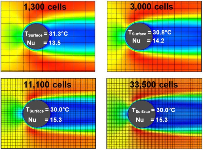
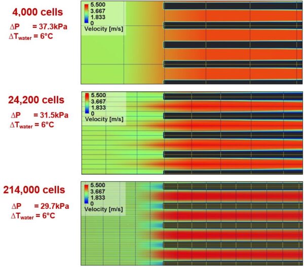
We’ve seen the term SmartCells a couple of times up to now, so let’s get into what it actually means. SmartCells describe the technology that allows Simcenter FLOEFD to adapt the calculation based on the information available from the CAD model. Consider the flow between two walls for example. SmartCells will automatically determine, if the mesh resolution is sufficient, or not, to numerically resolve the velocity profile within a given channel. If there is an insufficient number of cells, the solver will automatically resort to applying standard engineering textbook calculations for heat transfer and shear stress in such areas. This is referred to as the “thin channel technology”. Also, consider curved surfaces where any mesher would ordinarily facet such surfaces.
In Simcenter FLOEFD however, the actual geometry is known, and the boundary layer calculation can be adapted accordingly within these cells. This is where the CAD embedded nature of Simcenter FLOEFD is distinctly different to any other ordinary “CAD embedded” software. This has an added major benefit of allowing use of very coarse meshes (by any CFD standards) and still accurately represent the geometry, thus maintaining high geometric fidelity.
Simcenter FLOEFD can therefore produce practical engineering results within the minimum amount of time and user effort (again, with no solver crashes – have I mentioned that before…?). See the images below demonstrating the implementation of SmartCells at the hand of relatively simple geometry. For a good real-world example of the use of SmartCells in an industrial application, refer to Part 3 of this series.
Enhanced Turbulence Modelling
The enhanced turbulence modelling approach of Simcenter FLOEFD incorporates; 1) a proprietary modified k-ε turbulence model along with 2) a two-scale wall function, which will be discussed below.
1) Proprietary modified k-ε turbulence model
The modified k-ε turbulence model employed in Simcenter FLOEFD comes with a host of enhancements that separate it from the stock-standard off the shelf k-ε turbulence model. For example, the calculation of tasks dominated by rotational flows such as cyclone separators, which ordinarily is not feasible with the regular k-ε model.
Furthermore, Simcenter FLOEFD can automatically transition from laminar to transitional to turbulent flows using the same mesh resolution, eliminating the need for the user to do these calculations beforehand in order to determine which wall treatment and associated boundary layer meshing strategy to use. A feature that comes handy when doing parametric studies where the range of variations in flow velocities and/or geometric dimensions can potentially result in a design space that includes both laminar and turbulent flows.
2) 2-Scale Wall Function
A subset under the enhanced turbulence modelling umbrella of Simcenter FLOEFD is the boundary layer calculation. Here is where the core differentiation lies between Simcenter FLOEFD and other conventional CFD tools. The 2-scale wall treatment allows Simcenter FLOEFD to calculate the boundary layer as a “Thin” (Cell size >> BL thickness) or “Thick” (Cell size << BL thickness) boundary layer, a necessity when using a cut-cell cartesian grid to capture arbitrary complex geometric shapes. There are a lot of things to be said about the boundary layer calculation, but in a nutshell, it is a mix of analytical and semi-analytical (with empirical enhancements) methods that also combine different turbulence models within the single 2-scale wall function calculation. The solver seamlessly applies the correct version of the calculation without requiring any user intervention. It just works – simple as that!
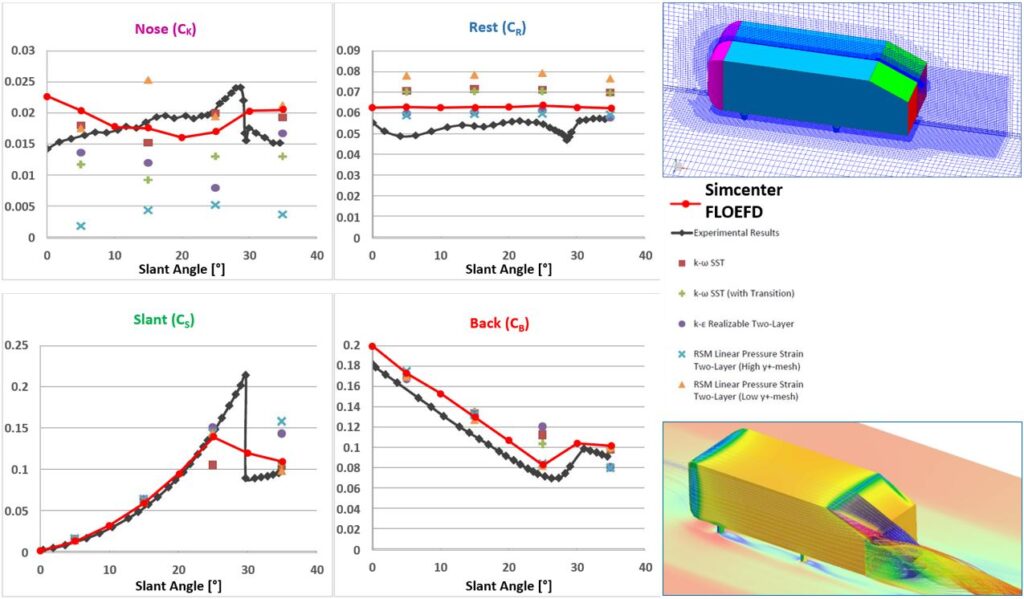
In order to prove that Simcenter FLOEFD’s enhanced turbulence modelling is actually very useful and even powerful, I would like to refer you to the image below extracted from Part 4 of this series where I conducted my own benchmark on the very well-known and well-documented Ahmed’s body (Ahmed, et al., 1984). Evidently, the enhanced turbulence modelling in Simcenter FLOEFD is capable of providing accurate and consistent results across a wide range of different flow phenomena, which typically requires different turbulence models in conventional CFD.
Conclusion
Here I have highlighted just the main technologies that distinguish Simcenter FLOEFD from any other CFD software. Simcenter FLOEFD eliminates most of the intricacies and finer nuances of CFD required to produce reliable results every time. There simply isn’t time in the real world to always do due diligence on testing various turbulence models, scripting or “programming” the mesher to accommodate any geometric changes in parametric studies or struggle with convergence issues etc. In Simcenter FLOEFD, all of this CFD-related clutter is packaged into a clean user-friendly environment. The user is therefore not confronted with all the numerics that influence the outcome of a simulation. The user only has to focus on the basics, i.e. getting the geometry, materials, environmental and boundary conditions, etc. correct and Simcenter FLOEFD can take care of the rest. Therefore, by introducing CFD for the design-engineer, product development is rapidly accelerated to meet and even exceed today’s productivity demands.
To see these different technologies in action, please continue reading the series where I aim to present how they work together almost unnoticed (to the untrained eye) at the hand of a few examples, see the links below.
Part 1: The Technology behind CFD for design-engineers
Part 2: Design and optimization of a flue-gas stack (Example of Simcenter FLOEFD for Design)
Part 4: Benchmarking the enhanced turbulence model of Simcenter FLOEFD in automotive aerodynamics


