Simcenter FLOEFD: CFD for Design-Engineers – Part 2
This is Part 2 of a 4-part series explaining the technology behind Simcenter FLOEFD. Here we will discuss how these technologies allow designers to use CFD for design and optimization. Part 1 introduced some of the main technologies that make the above statement possible. Part 3 will look at a real-world example of how the Smart Cells in Simcenter FLOEFD are used. Part 4 demonstrates the enhanced turbulence modelling capability of Simcenter FLOEFD (links to the other posts provided at the end of Part 2).
CFD for design and optimization of a flue-gas stack
Simcenter FLOEFD for the Designer
In order to demonstrate how Simcenter FLOEFD can be used by designers, allow me to take you on a trip down memory lane… The year is 2007. A bright-eyed and bushy-tailed mechanical engineering student in my final year. I had just been introduced to Simcenter FLOEFD (back then it was called “EFD”) while doing vacation work at MSC-Africa (the reseller for “EFD”). I was ready and eager to tackle my final year design project, chosen specifically because it was a “CFD topic”. It explicitly required the use of CFD for the design and optimization of a flue gas-stack. Most of us (students) would otherwise have avoided CFD projects like the plague because up to that point, we’d had zero exposure to CFD. We’d be left to our own devices to gain a working knowledge of CFD. I even recall my supervisor telling me that he would not be able to assist me if I used “EFD” and that he didn’t believe in these “black box” CFD tools…Okay, challenge accepted!
Project description
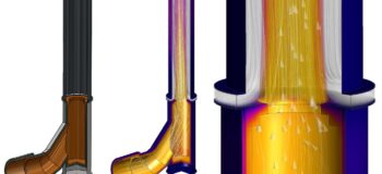
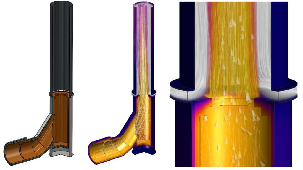
Hot gas coming from a liquor burner at 950°C must vent through a chimney stack at the required minimum height of 15m. The aim was to save on construction costs by using a 9m long steel pipe for the stack instead of building from refractory brick up to the required height. The maximum allowable temperature on the steel pipe was 350°C, therefore the hot gas needed to be cooled sufficiently. Cooling of the gas was to be established by throttling the gas through a venturi at the end of the stack base and allowing ambient air to be drawn in by the low pressure induced by the venturi.
Objective
Use CFD for the design and optimization of the venturi geometry, air slip-gap size and pipe diameter to minimize cost and weight.
Constraints
Maximum temperature = 350°C. Solution must be practical.
So, I got cracking immediately. I remember never even bothering with simplifying the model and just going all out from the start. Full 3-D (not even bothering with 2-D or even symmetry), heat conduction in the solids (including the refractory material, insulation layer and steel outer shell) and specifying the flue-gas as a mixture of the various gases. Even so I was able to start producing results immediately, literally! It took longer to generate the CAD model than to set up and run the first simulation. I could spend my time investigating pretty much all options for the venturi geometry and air gap combinations by simply utilizing the available CAD modelling and parameterization features. There was no need for any macros or programming of the mesher to accommodate all the geometry changes I threw at the software.
Just to prove my point, I still have the assembly from that time, and even after 13 years when I opened it up, there everything was, just as I had left it…I could simply setup the flow projects (using the project report as reference) and rerun the simulations. Here you can see the combinations of venturi shapes with different stack pipe mount options, i.e. on top of or overlapping with the base, considered during the concept evaluation phase.
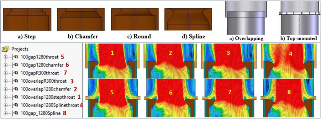
Running through all of the combinations was as smooth as silk and I could pinpoint the most feasible design concept very early on in the project. A 2-stage concept evaluation process, which considered the costs of fabrication and material, weighed against the performance benefits, revealed that the combination of a stepped throat and a top-mounted stack was simply the most feasible combination. Yes, one could argue that just by thinking about it most of these concepts could’ve been ruled out, but then where’s the fun in that? Especially when it is so simple and quick to explore those “out of the box” ideas? It isn’t called “Design Exploration” for nothing…
The next step was the optimization of the selected concept. Back in those days there was no built-in optimization capability like there is today, i.e. the “Extended Design Exploration Module” with the Simcenter FLOEFD embedded HEEDS solver. [Sigh]…If only I could travel back in time… Alas, I had to rely on external optimization software. I used the Design of Experiments (DOE) with a response surface approximation approach. The input variables of the DOE were;
- Throat diameter
- Pipe diameter
- Slip-gap height
- Venturi centre offset
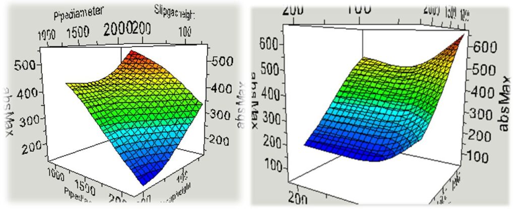
The CAD configurations associated with the DOE design points were automatically populated from an Excel spreadsheet (again standard CAD functionality, no programming involved). The main flow project was simply “cloned” to all the DOE configurations and all 40 designs were ready to run immediately. However, solving all 40 designs on my dual-core 750MB RAM computer would’ve taken 40 days, but I was fortunate to run them on the training computers at MSC-Africa. The straightforward “Batch Run” functionality in Simcenter FLOEFD (“EFD”) made this a breeze, even in those days. After a week or so I collected the DOE study results and loaded it into the optimization software again to generate the response surface upon which the optimization was conducted. See some examples of the response surfaces below. The optimization objectives were;
- Minimize cost
- Minimize temperature variation (ensure uniform distribution)
- Maximum temperature constraint = 300°C (upper constraint due to uncertainties in accuracy of the response surface approximations).
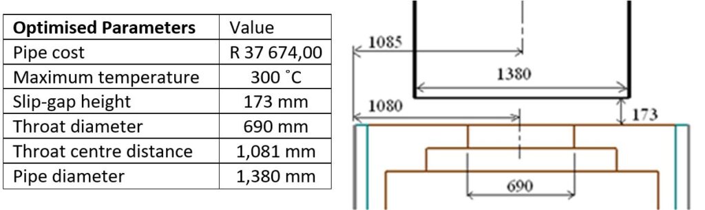
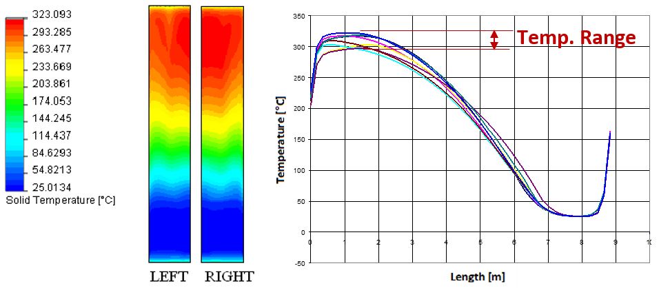
The optimum design parameters according to the response surface are shown below. To verify this result, the optimum configuration was quickly analysed using the proposed parameters, shown below. The actual maximum temperature was 323°C, only 7.67% higher than the response surface predicted, but still well below the 350°C limit. The temperature distribution was also acceptably uniform as shown in the image below.
Conclusion
Thinking back on this work and reading through my report I can hardly believe the amount of success I was able to achieve, all thanks to the revolutionary “black box” CFD, which evidently was decades ahead of its time. If you think about it, this was done in 2007, but most of this capability was already available years before I got my hands on it.
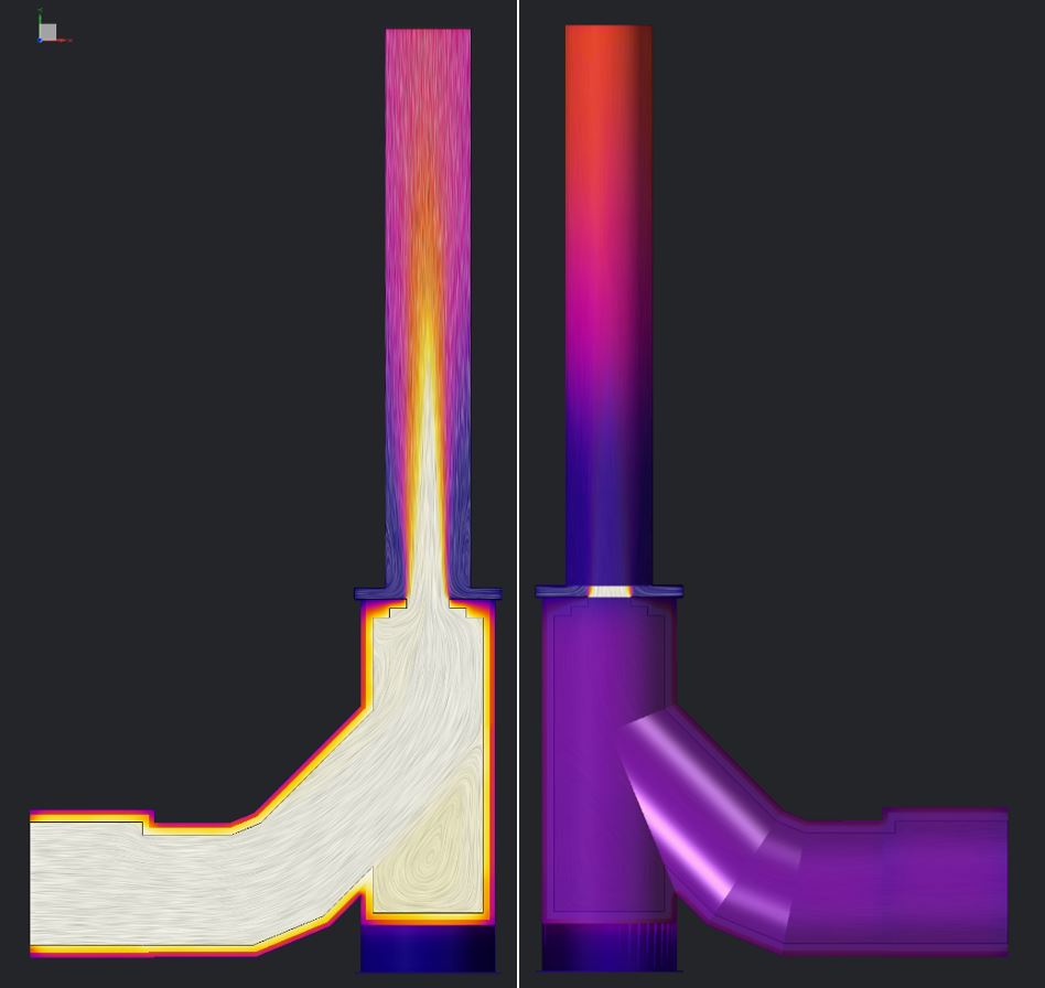
Sure, nowadays there is so much more functionality and additional physics, but the core technology that makes Simcenter FLOEFD truly unique has always been there. To wrap up, I can safely say that Simcenter FLOEFD is indeed a truly effective designer’s tool. Designers can use CFD for the design and optimization of products, freeing up engineers to spend time on further developments. And with that, I leave you with a “pretty picture” followed by the links to the rest of the series. Continue to Part 3 for a real-world example of the use of the Smart Cells technology in Simcenter FLOEFD…
Part 1: The Technology behind CFD for design-engineers
Part 2: Design and optimization of a flue-gas stack (Example of Simcenter FLOEFD for Design)
Part 4: Benchmarking the enhanced turbulence model in Simcenter FLOEFD for automotive aerodynamics


