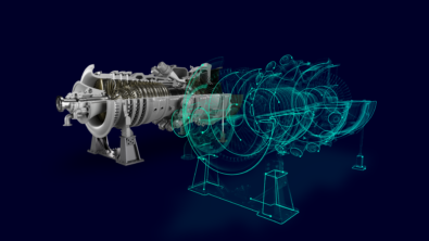
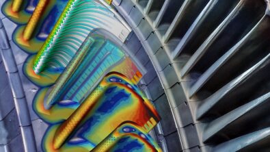
When cold-to-hot transformation plays a role in turbomachinery
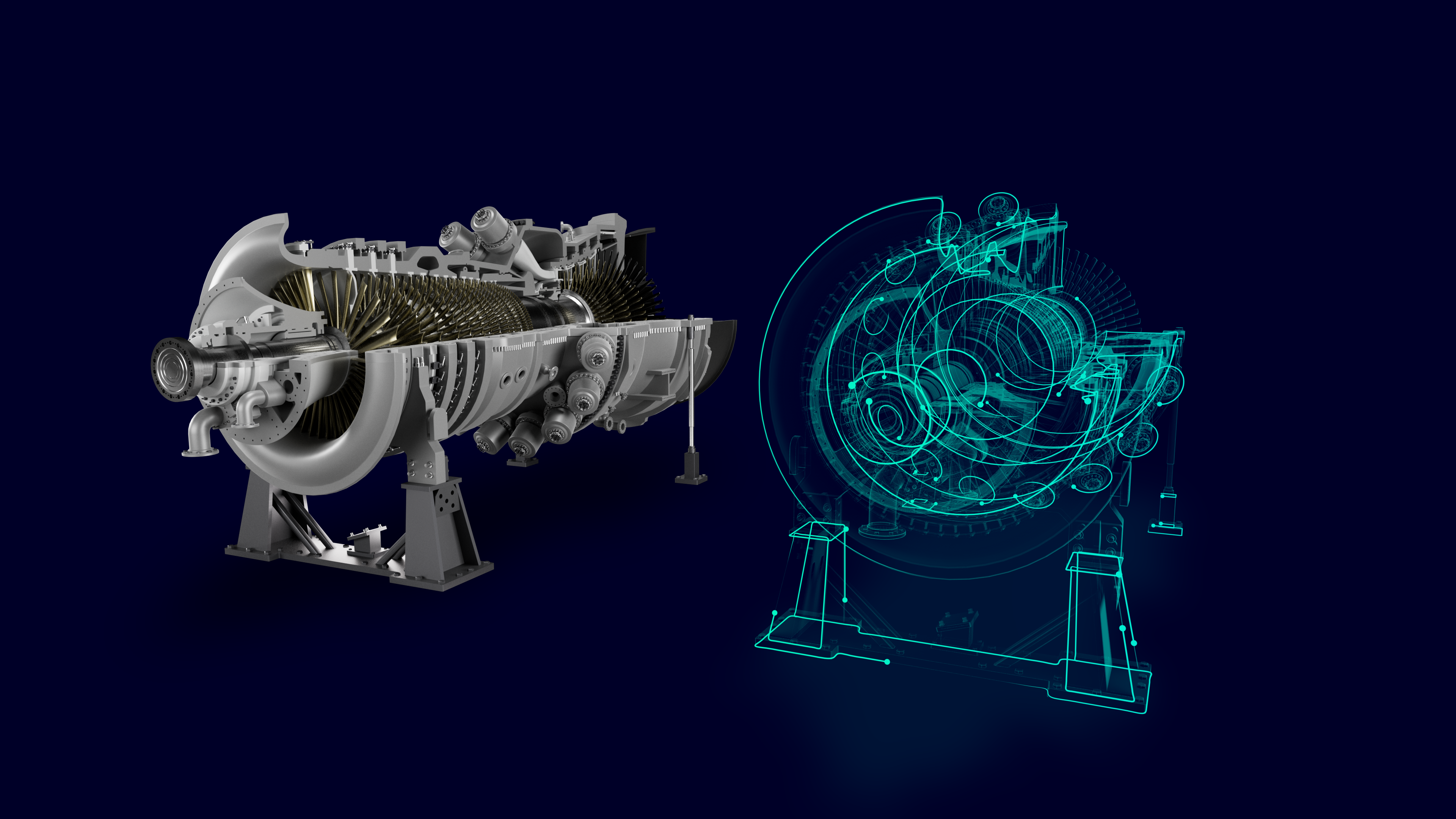
The impact of geometrical changes on performance and durability
Turbomachinery engineers and designers face a significant challenge when it comes to dealing with the geometrical changes that occur between unloaded and loaded operational conditions. These changes not only impact the efficiency and power of turbomachines but also affect their durability and lifespan. To accurately predict and represent the behaviour of a real engine, engineers and designers must consider these geometrical changes and (i.e. cold-to-hot transformations in turbomachinery) when designing affected components.
In addition to the typical design challenges, the digitalization and integration of digital threads offer even greater potential for customizing and optimizing turbomachinery components according to customer specifications. The digital thread serves as the foundation and framework for a more integrated and connected engine development process, starting from the initial requirements and architectural specifications and continuing until the engine is in operation. Throughout each stage of development, valuable data is generated. By connecting and analyzing this data in a meaningful way, engineers can gain additional insights and identify areas for improvement.
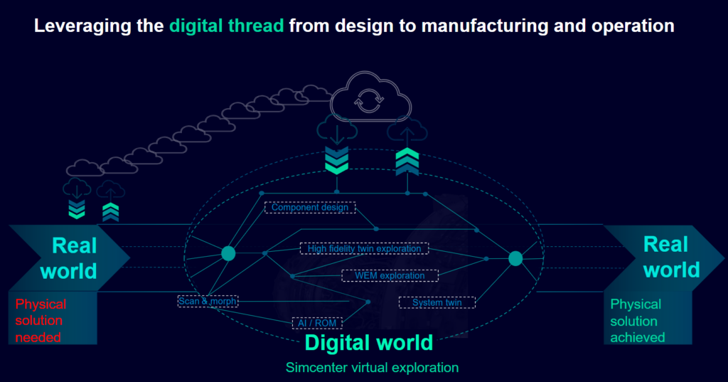
A practical example can be seen in the close connection between design, manufacturing, and operation.
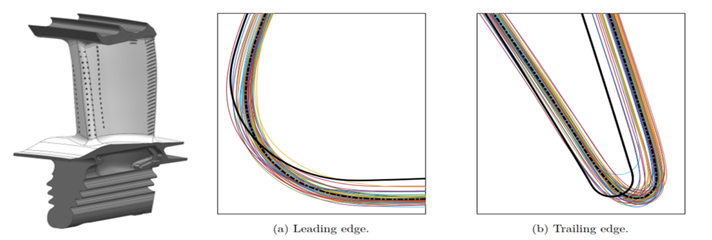
Due to environmental conditions or other external factors, the final manufactured components may deviate from their digitally designed ideal shape. These deviations can fall within specified limits or exceed them significantly. Components that are outside or at the limit of tolerance can have unknown effects on the engine’s performance and durability. In the case of critical parts, the typical solution is to discard them. However, what about components that are on the border of tolerance?
Sometimes, the impact of these deviations is only discovered during final performance tests, which is often too late and requires disassembly to replace related parts. Wouldn’t it be valuable to anticipate the possible impact in advance? Furthermore, wouldn’t it be even more beneficial to leverage these deviations and fine-tune the final assembly by selectively choosing parts to better meet the final requirements?
The CAD-centric cold-to-hot transformation approach in turbomachinery
In the aero engine industry, it is common practice to inspect and scan critical components, especially those subjected to rotation or thermal loads, after manufacturing and storing the collected data. It would be beneficial to leverage this data by connecting it with the design process to virtually explore real-life components that may slightly deviate from their digital counterparts.
To achieve this, one can start by virtualizing the physical “as manufactured” part and comparing it to its digital “as designed” twin. By capturing measurements from a physically manufactured component through scanning or manual techniques, one can manually adjust the CAD representation of the part or utilize reverse engineering techniques, such as morphing a CAD file to match the scanned STL data set.
The subsequent step involves a cold-to-hot transformation in turbomachinery, which entails transforming the unloaded “cold” condition of the component to its operational loaded (“hot”) state. This enables a digital assessment and evaluation of the performance deviation compared to the results obtained during the design phases.
The Simcenter portfolio, a part of the Siemens Xcelerator business platform, provides a fast and efficient method for determining the geometric changes that occur when transitioning from an unloaded to an operational loaded condition (cold-to-hot transformation). This approach follows a CAD-centric transformation approach, ensuring that the resulting transformed CAD retains its attributes and characteristics, including naming conventions. This allows for seamless integration into existing simulation workflows, such as mechanical and aerodynamic analyses.
The process begins with a cold “as manufactured” CAD representation of the component and concludes with a loaded “as operated” CAD representation. The approach follows a nonlinear methodology, which enables the consideration of nonlinear material behavior, viscoelastic deformation, and nonlinear contact conditions.
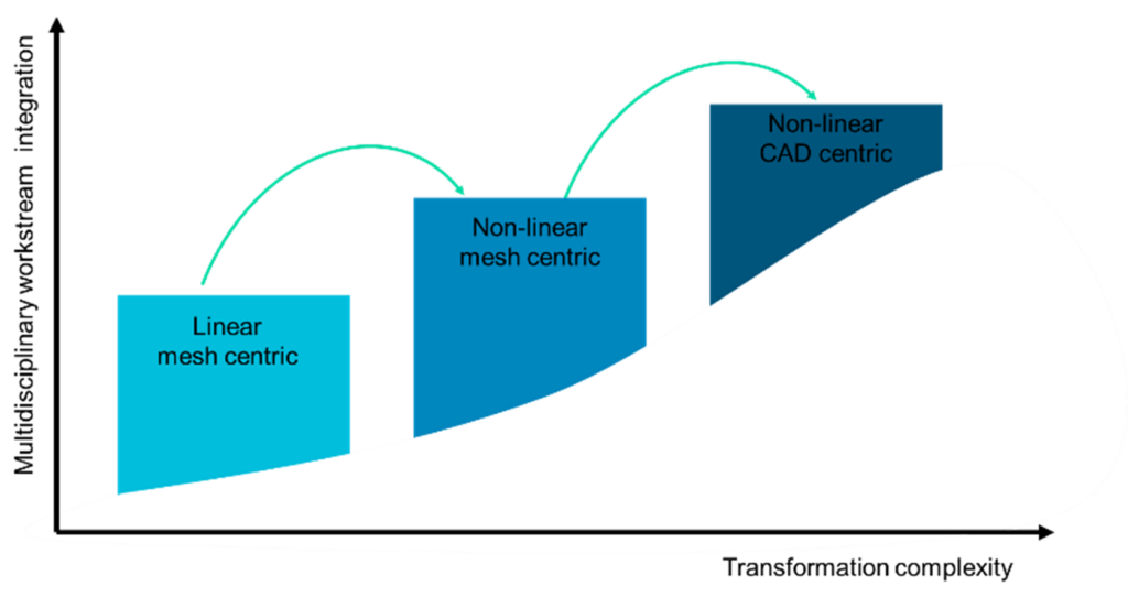
By considering such nonlinearity, it becomes possible to accurately simulate complex geometry transformations, such as shrouded blades with deformation-constraining contacts. This ensures that the generated representations closely mimic the real behaviour of a manufactured part under actual operational conditions. The CAD-centric approach allows for seamless integration of the deformed component representation into simulation data sets, including those obtained during the design phases. As a result, a comprehensive virtual exploration of the real manufactured part can be conducted.
In our example, the CAD cold-to-hot transformation is performed using Siemens NX software, utilizing either the NX global deformation functionality or the additional OmniFree application. To enable CAD morphing, the deformation must be known. This is achieved through an iterative coupled numerical approach involving Simcenter STAR-CCM+, Simcenter 3D, and Simcenter Nastran, ensuring the highest fidelity of results.
Workflow demonstration with the NASA Rotor 67
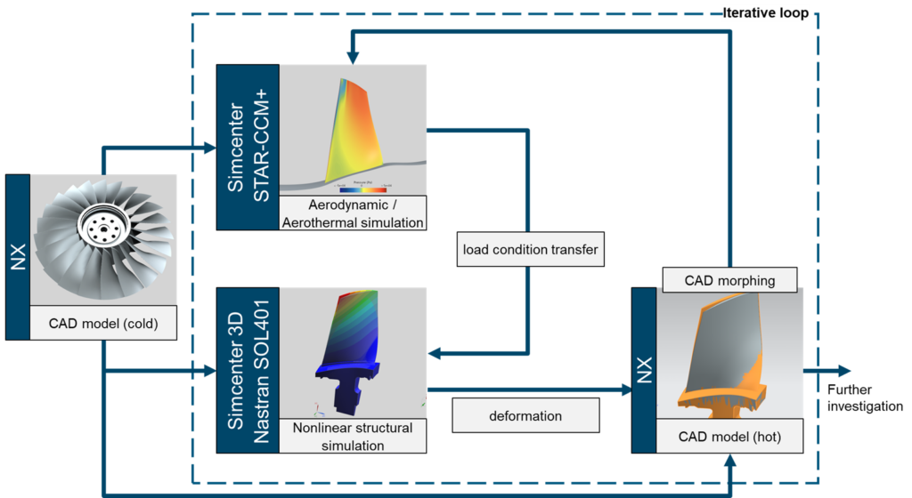
To illustrate the workflow, we can use the widely recognized NASA Rotor 67 as an example. The geometry and boundary conditions for this rotor have been obtained from open literature sources2 3 4. The process begins with the transfer of a cold CAD part from Siemens NX directly to Simcenter STAR-CCM+. In Simcenter STAR-CCM+, operational fluid and thermal loads are applied to the CAD model. As an initial outcome, aerothermal and aerodynamic loads acting on the blade can be obtained.
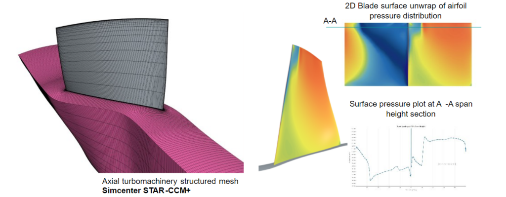
These blade loads are subsequently utilized as boundary conditions for the next step in the process, which involves conducting a finite element nonlinear structural analysis using Simcenter 3D. The analysis is performed using the Nastran nonlinear solver SOL401, allowing for the calculation of the deformation of the component.

The output of the nonlinear finite element analysis yields valuable information about the deformed mesh. This information is then exported as an STL file from the Simcenter 3D post-environment and transferred to Siemens NX CAD software. In Siemens NX CAD software, the CAD transformation is performed by morphing the initial cold CAD representation to match the obtained hot mesh deformation.
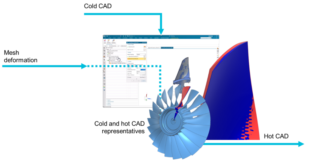
The result of this workflow is a deformed CAD representation, which can be further utilized as a CAD part in a CAD-centric CAE process. Through this fully embedded CAE workflow, Simcenter empowers engineers to conduct rapid and precise sensitivity and comparative studies. It also enables improvements and accelerates multi-design and optimization workflows within the design phases of turbine engine components.
To illustrate this, an artificial deviation was introduced to the NASA Rotor 67 by manipulating the blade stagger angle by 2 degrees. The newly generated “as manufactured” CAD representation was then subjected to the iterative simulation approach to quickly assess the performance deviation under the same operating conditions as the originally designed design. This process does not require setting up new simulations; the only step necessary is to replace the CAD part and re-run the simulations. All settings, boundary conditions, post-processing, and workflow connectivity steps can be automated. This allows for a seamless change in geometry with just a single button push, utilizing Simcenter HEEDS to orchestrate the simulation workflow.
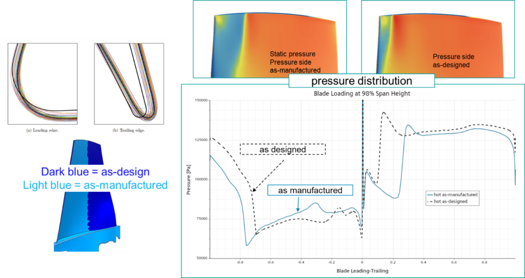
The showcased workflow offers engineers, designers, and analysts a rapid and precise method to perform CAD-centric geometry cold-to-hot transformation in turbomachinery while considering realistic boundary conditions and real-life deformation characteristics. It provides a fast and accurate approach for achieving the most accurate representation of the geometry transformation process.
- 2018, Kamenik, “Robust Design of Film-cooled High-pressure Turbine Blades in the Face of Real Geometric Variations”. ↩︎
- 2021, Keener, “Design and Dynamic Characterization of the OSU Rotor 67 Blisk for Future Damping and Mistuning Studies at Design Speed” (Master Thesis) ↩︎
- “catalogues aubes” gitlab project from Polytechnique Montréal, ↩︎
- National Archives Catalog ↩︎
