What is new in NX | Thermal Simulation
Welcome back to another entry in the What is New in NX™ software blog series for the summer 2022 release. This post is going to outline the new features to help you successfully run comparative thermal simulations. To help set the stage, the example we will be referring to is a rear cover design with and without cooling holes. Simcenter FLOEFD software puts the power of computational fluid dynamic (CFD) simulation right at your fingertips. To better prepare us for this example, let’s take a look at what CFD is all about.
Benefits of Thermal Simulation
Computational Fluid Dynamics refers to the simulation process that can replace or add on to your experiential and analytical methods. In comparison to prototyping and creating elaborate experiments, CFD can help engineers design and analyze products more efficiently. In more common terms, these simulations create the perfect “what-if” scenario to assess what the best overall design can be. This in turn leads to faster design solutions at a fraction of the price.
Now that we further understand the use of the software, the idea of successfully completing a thermal simulation seems much more realistic. Let’s get into the specifics!
Frontload all CFD simulation inside of NX
One of the most attractive new features within NX is the power to embed other software into your workspace. In our scenario of thermal simulation, Simcenter FLOEFD is embedded directly into NX. This means that you do not have to learn new software and, most importantly, can continue working in an environment that is native to you. Another powerful addition to this software is that by embedding Simcenter FLOEFD into NX, the changes that you make are automatically detected and synchronized to your design.
Utilize component control to select geometry
The next step is to exclude any geometry that is going to be replaced later on. For this we will need to utilize the component control to tell Simcenter FLOEFD to ignore the pre-determined geometry. In this specific example, there is no need to include the mechanical computer aided design (MCAD) printed circuit board (PCB). Phew! That was a mouthful but an equally important concept to pay attention to. Now, the MCAD PCB will be replaced later on with the thermal representation that we are currently on our way to creating.
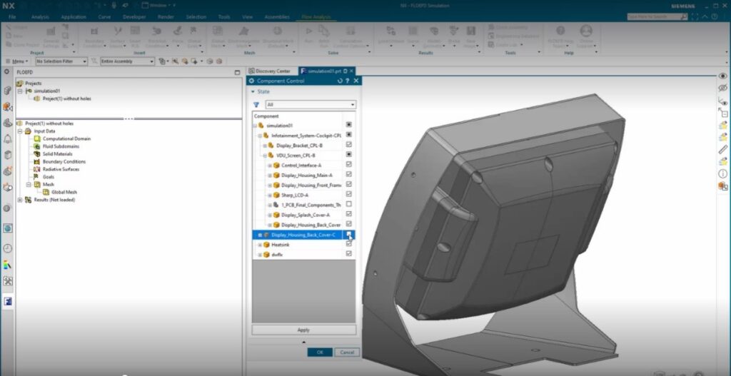
Top Tip: Using Component Control like this eliminates the need to delete or hide items from the CAD (computer aided design) assembly. This can save you from bigger problems presenting themselves down the line.
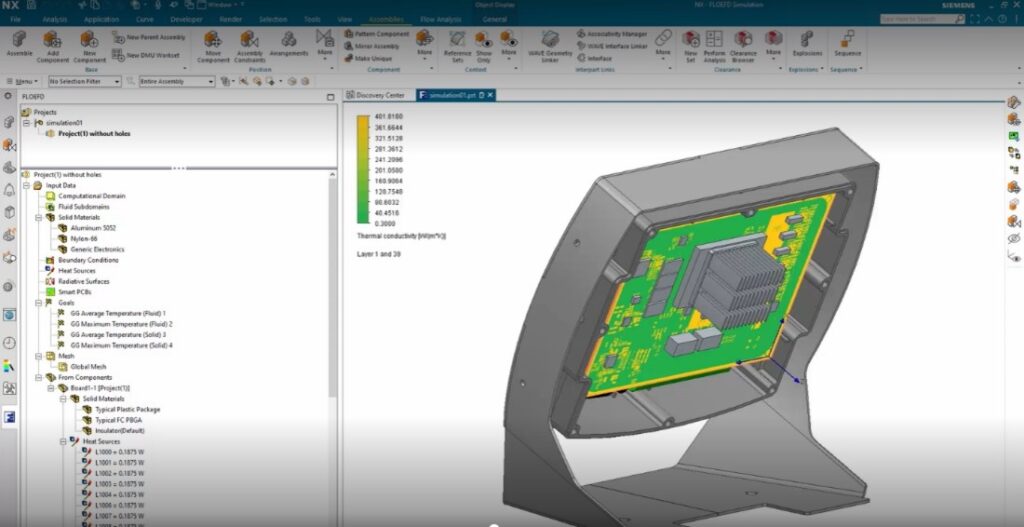
Creating a thermal representation with EDA Bridge
Now that we have selected the components that we need, let’s turn our attention to the PCB in this example. The problem with the current PCB is that while it is the perfect physical representation, it lacks the necessary information we need to complete the thermal simulation. This is where Simcenter FLOEFD’s built in EDA (electronic design automation) Bridge tool comes into play. EDA Bridge reads the PCB design file directly and can export it into a thermal model with the aligning material properties.
Utilize Smart PCB technology to predict more accurate component temperatures
- Works by modeling the PCB as a huge network assembly
- Enables detailed copper distribution
- Minimal additional computational overhead
Fast Fact: It has been found that users can reduce overall simulation time by 75% and enhance productivity by up to 40x when using Simcenter FLOEFD.
Source: Siemens PLM Software, Simcenter FLOEFD: Frontload CFD simulation inside your CAD software
Cloning for comparison
After your thermal representation of the PCB has been completed as a sub-assembly, you can now use the “Add from Components” feature to re-enter all the inputs back into the original model. Along with the new PCB, you can also select and replace the component model for the processor with a more detailed model to better represent the thermal conditions expected. This detailed model of processor could be imported, or a new model can be created using Simcenter FLOEFD’s built-in Package Creator. In our case, adjusting the specifications of the package to match those of the microprocessor in the model is the best way to get the results we are looking for.
Reminder: Simcenter FLOEFD can read electronic component models in a variety of formats. This includes the industry standards, files created in Package Creator and any other unique file types. This is important, because it makes it easier to increase the levels of fidelity and predict component temperatures at slimmer margins.
Clone the model and solve
Once the PCB sub-assembly is reviewed and closed, return to the main simulation model. Before running the simulation, remember to create a second simulation. This is so you can compare how the modified covers with cooling holes perform versus the standard rear cover. The next step is vital in completing the simulation correctly. Before solving the projects, you need to tell Simcenter FLOEFD to ignore your original model and include the modified model that you are experimenting with. It is now at this point that we can solve both projects.
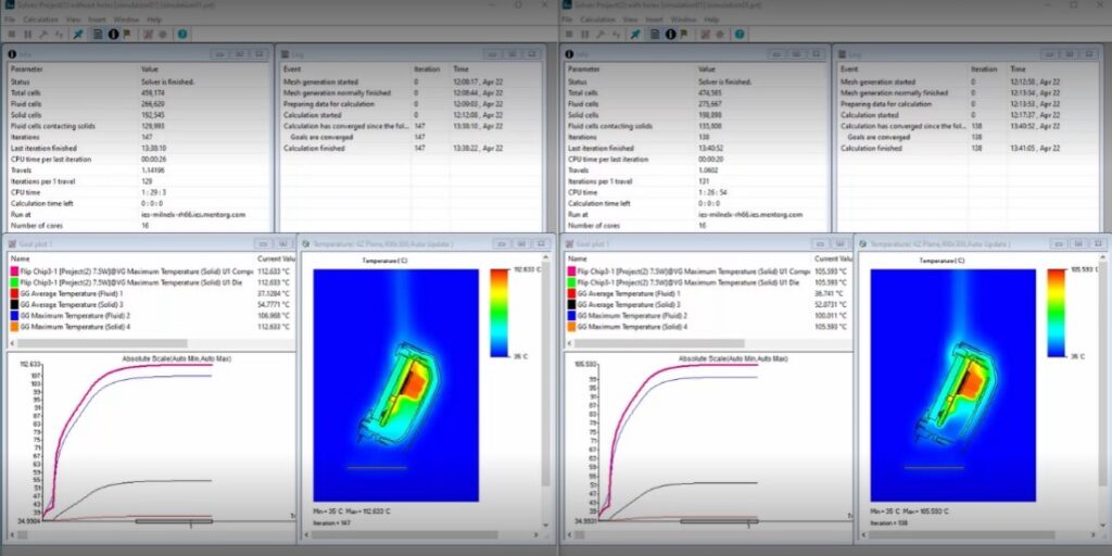
Reviewing thermal simulation results
Once both simulations have finished, you are now ready to review the results. In most cases, it should be clear the impact the experimental model has on the thermal dynamics versus the stand model. By utilizing thermal simulations, we have been able to clearly and efficiently find the impact that two contrasting designs can have on your model without ever leaving NX.
Summary
We hope you have enjoyed following along through this example. Running thermal simulations throughout the design process can be a great way to be confident in the thermal characteristics of your product without ever having to leave NX. Remember to check back in to learn about more new features coming out in the June release of NX.
Continue your journey with NX
Comments
Leave a Reply
You must be logged in to post a comment.
I wonder if heat dissipation parametric/topological optimization will be implemented in the near future. Would definitely be a welcome feature to NX.