NX Tips and Tricks | Sketch Slot Command
Introduction
Welcome to a brand new year with NX™ software! This is the first episode of our brand new tips and trick series, where we are focusing on new capabilities added to the December 2023 release of NX. If you want to get a broader understanding of these capabilities, take a look at our release blog we released just before the Christmas holidays.
The NX tips and tricks series; what is it?
The tips and tricks series takes a closer look at new capabilities added to NX, and provides you with the know how to best integrate them into your own workflows. We will typically take you through a specific workflow to show you how to implement a new function, and why it can benefit you.
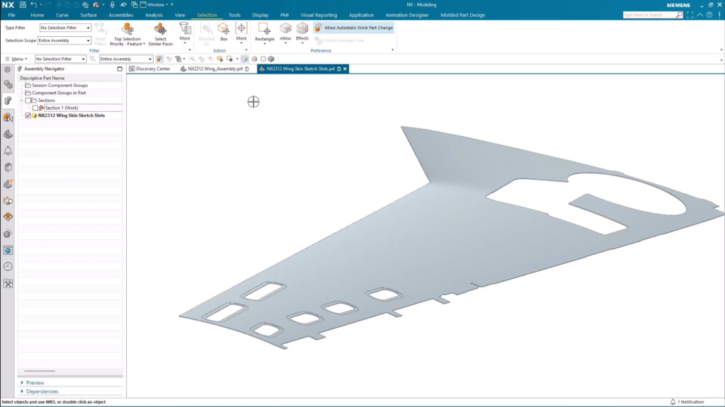
Our first episode for this new release focuses on the brand new Sketch Slot command. We’ll be using this command to create a range of inspection holes on the underside of an aircraft wing. Let’s take a look!
Creating profiles using the new Sketch Slot command
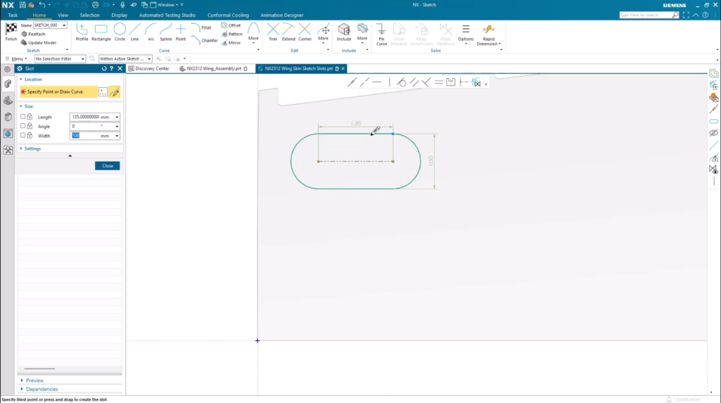
The first place to start is by navigating to the new command from our menu options in NX. You’ll find the tool under Home > Curve > More > Slot. It’s really easy to navigate to, and means we’re now prepped to start creating the slots for the inspection holes.
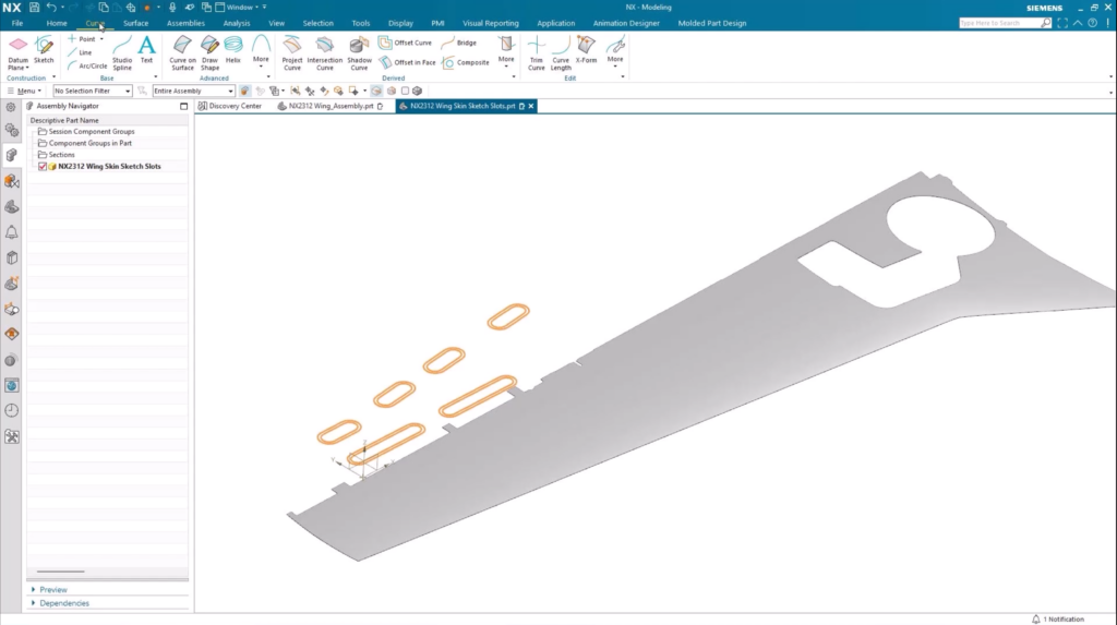
Creating the slots
We’ve focused on ensuring the creation of slots is as easy as possible. So, all you need to do is pick your first point, pick your second point and then drag to create the width of the slot. Additionally, you can also lock the size of the slot so that you can quickly generate another slot of the same size. This is important for our use case, but can save time in a range of other workflows too!
TOP TIP:
When you select the center line of the previous slot when creating your new slot, they will both be automatically aligned.
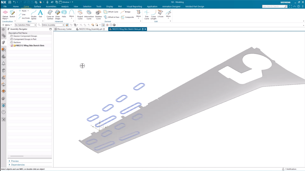
Creating inspection holes along the wing edge
It’s also important for this use case to create inspection holes along the trailing edge of the wing too. The goal here is to ensure better access points to issues that may arise within the internal workings of the plane. There are a few ways that this can be achieved using the Sketch slot command:
- Measure the angle of the trailing edge and input the size into the slot parameters.
- Construct a reference line and use that to align the new slots to create.
In this instance, we’ll use the latter approach. Any slots created will follow the length of the reference line. As long as the construction of the slots touch the reference line, they will follow the trailing edge of the wing.
TOP TIP:
You can add a distance dimension to ensure your aligned sketch slots stay a consistent distance away from the edge your geometry. You’ll notice any changes made to the distance will be applied to all of the sketch slots created.
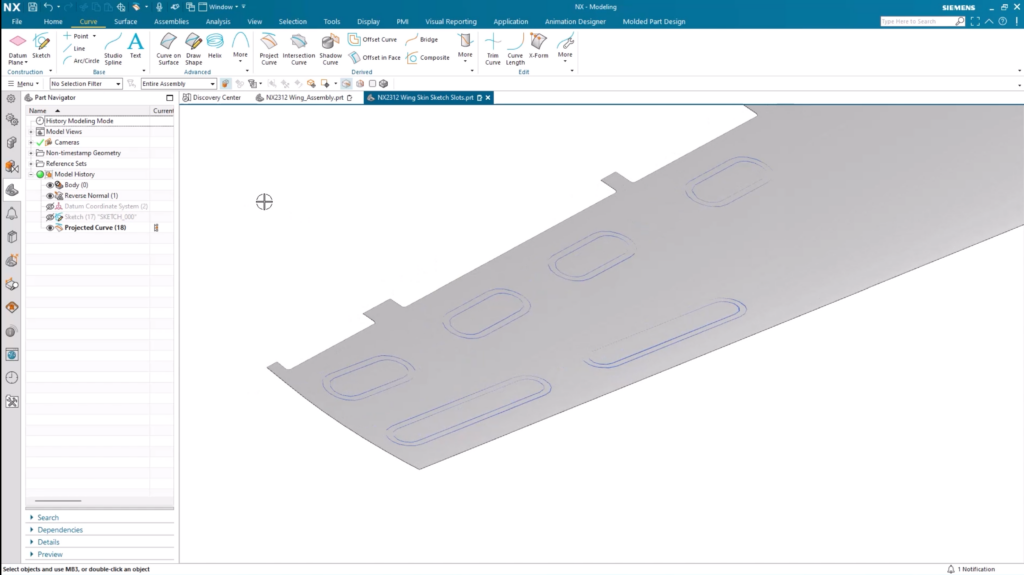
Projecting the sketch slots onto the skin
We need to make sure that the sketch slots are projected directly onto the wing surface. Any sketch slots that have been created will be automatically selected, and from there it is a relatively straightforward task. We simply need to select the wing surface and the direction of projection. Once these tasks are completed, the sketch profile for the inspection holes will be laying directly on the surface of the wing.
Creating the holes using the Thicken command
With the sketch profile projected onto the wing, the next step is to go ahead and create the holes themselves. The best way to do this in NX is to use the Thicken command, which can be found under the Surface tab. In this use case, we’re first focusing on the inner boundary of the projected curves; it will all make sense in this next paragraph. It’s simply a case of selecting the inner boundary curve, and clicking on the sketch profile of our slots. It really is as simple as that.
You’ll notice that we created an inner and outer boundary for our sketch curves, and there’s good reason for that. We need to make sure there is an area of different thickness around the access hole, which will help to define a recess where the access hole cover door will be seated. It’s another very simple step; we simply need to select the outer boundary curves with the desired offset.
Applying material to multiple faces with embedded Artificial Intelligence
The sketch profile has been created and projected onto the wing skin, whilst we’ve also added a recess to our sketch. It’s also important to ensure that there’s enough material on the outer wall of the recess. If there isn’t, the structural integrity of the recess could cause issues. With NX, we can use Artificial Intelligence to ensure an offset is applied to the face of the recesses.
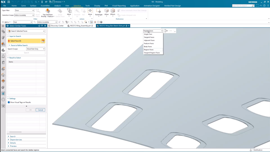
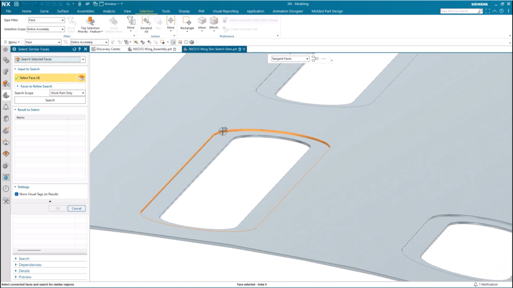
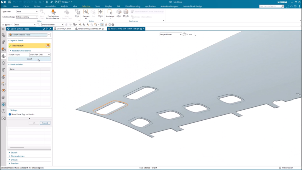
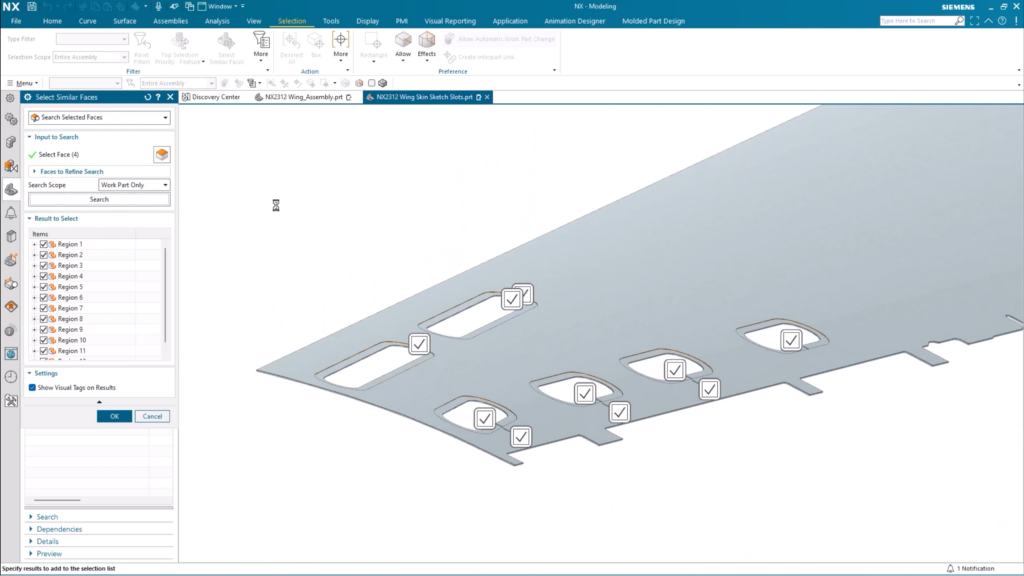
With the faces identified, it’s possible to add the extra offset required at this stage.
TOP TIP:
At any point, changes can be made to the wall thickness if it’s not quite right. We simply navigate back to the Thicken command and make any desired changes. You’ll notice that any changes made to one recess will be made on the rest of the recesses too.
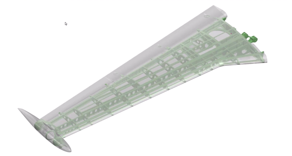
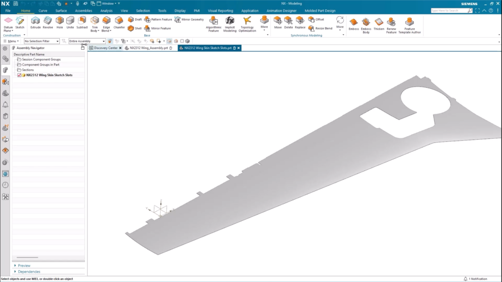
The finished product
Using the new Sketch slot command means we’ve taken a standard plane wing and applied the necessary inspection holes. Here’s a comparison our wing before and after creating inspection holes.
Continue your journey with NX
This is the first entry for the December 2023 release of NX. Keep checking back over the coming weeks to see other helpful tips you can implement into your workflows. Thanks again!
Watch the Sketch Slot YouTube video here ▶️
Take me to the NX design blog 📚


Contact the NX team today 📲