Multi-body Holes and Threads | NX Tips and Tricks
Welcome back to another installment in the tips and tricks series. Today, we will be covering multi-body holes and threads. Holes are one of the most common features in any mechanical design. They are used to connect parts, insert fasteners, reduce weight, and more. However, creating holes in NX™ software can sometimes be tricky, especially when dealing with multiple bodies, different types of holes, and complex patterns. In this blog post, we will share some tips and tricks on how to create holes in NX more efficiently and effectively.
Create holes that pass through multiple bodies
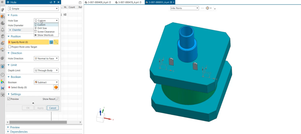
Sometimes, you may need to create a hole that passes through more than one body within a part. For example, you may have a part that consists of several extruded or revolved features that overlap each other. In this case, you can use the Select Body section within Boolean under the Hole command to choose which bodies are cut through by the hole. This way, you can customize how the hole interacts with each body and avoid unwanted results.
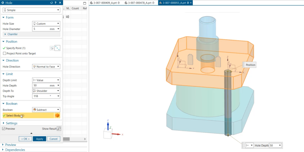
To use this feature, simply select the Hole command from the Home tab and choose the type of hole you want to create (simple, counterbore, countersink, or tapered). Then, under Boolean, click on Select Body and select the bodies that you want the hole to cut through. You can also use the Ctrl key to select multiple bodies at once. You can then specify the position, direction, size, and depth of the hole as usual.
Try Hole Series when the bottom part of an assembly hole must be threaded
Hole Series is a great tool for when you need a more tailored approach to connecting multiple bodies. Hole Series allows you to control the fit, as well as threading for each body that your hole passes through. This is important when screws and fasteners are only partially threaded or change sizes between connections. Hole Series also automatically recognizes which bodies are cut through, speeding up hole creation. You can choose from pre-created screw options or customize a size to best fit your part.
To use this feature, select the Hole Series command from the Home tab and choose the type of screw you want to use (standard or custom). Then, select the faces or planes where you want to place the hole series. You can also use the Ctrl key to select multiple faces or planes at once. You can then adjust the parameters of the hole series, such as fit type, thread type, clearance type, diameter, depth, and pitch. You can also preview how the hole series will look like before applying it.
This feature is very useful when you need to create holes that connect multiple bodies with different types of screws and fasteners. It allows you to create more accurate and realistic designs and ensures that your parts fit together properly.
Utilize Pattern Geometry to speed up creation of uniform features
Pattern Geometry is a powerful tool to use when replicating your features across a part. With pattern options including linear, circular, and polygonal, it is very easy to match the design pattern in your part with the layout of its features. This tool is great for expediting feature creation in uniform parts and can also ensure consistency in features created. Within pattern geometry it is easy to control boundaries, orientations, and variance of replicated features. This ensures that the design process moves as smooth as possible.
To use this feature, select the Pattern Geometry command from the Home tab and choose the type of pattern you want to use (linear, circular, or polygonal). Then, select the feature or features that you want to pattern. You can also use the Ctrl key to select multiple features at once. You can then specify the parameters of the pattern geometry, such as direction, spacing, angle, count, offset, rotation, scale, and so on. You can also preview how the pattern geometry will look like before applying it. This feature comes in handy when you need to create features that follow a certain pattern or symmetry in your part. It allows you to create more efficient and consistent designs and saves you time and effort.
Continue your journey with NX
We hope that these tips and tricks will help you create holes in NX more easily and effectively. Holes are an essential part of any mechanical design and knowing how to use the different tools and options available in NX can make a big difference in your design quality and productivity.