Considerations for rigid-flex design
Rigid-flex design introduces several challenges that many of today’s design tools cannot handle. These could include:
- Multiple layer stackups
- Bend areas with specific design rules
- Unique trace geometries such as tapered traces
- Collaboration with the MCAD team
The best way to achieve first time success when designing with rigid flex is by using a correct by construction design methodology from stackup definition through manufacturing handoff that includes PCB bend areas, region rules (vias, traces and plane types) as well as visualization in an integrated 2D and 3D environment. Let’s dig deeper into each of these considerations.
Multiple layer stackups
A rigid-flex design will typically have multiple stackup areas for different purposes, such as embedded, adhesive, bikini cover layers, or stiffener, making Intelligent stackup definition a necessity.
Bend areas
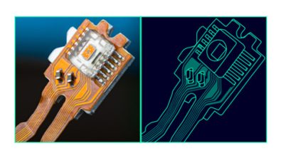
Unlike a typical PCB design, the rigid-flex region will physically bend, introducing new design and manufacturing issues. The PCB design tool must be able to define and understand a bend area and how that area will physically move. This has impact on if and how components can be placed on the area, and if and how routing can be implemented.
Unique trace geometries
When routing in a bend area, tapered traces may be required to improve reliability. Depending on the “bend,” any angle routing and arcs would be necessary. When editing, efficiency can be increased if the editor has the ability to push and shove these arcs in the design software.
ECAD/MCAD collaboration
Designs with rigid flex, by definition, will need to bend in a specific way to fit into their enclosure. Collaboration with the mechanical engineering team and the MCAD tool is a must. This can be accomplished via ProSTEP and the IDX format which will send incremental updates and notifications bi-directionally between the ECAD and MCAD tools allowing both groups to visually validate designs with photorealistic 3D to minimize iterations. This process also includes automatic 3D design rule checking to identify any electro-mechanical conflicts.
Rigid-Flex design with PADS Professional Premium
Accelerate layout of a rigid-flex board with PADS Professional Premium, a tool that understands bend areas and other unique flex geometries, including placing irregular angles and the ability to employ rich routing capabilities for rigid-flex designs.
To learn more about rigid-flex design with PADS Professional Premium download our ebook.