Back-annotating DFM enhancements to place & route tools
By James Paris, Mentor Graphics
Back-annotation of DFM enhancements to P&R simplifies iterations as designers close timing and physical verification
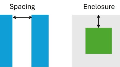
Design for manufacturing (DFM) tools and processes are designed to find yield optimization opportunities in layouts through the use of a variety of interconnect and base layer enhancements, such as via doubling, via enclosure expansion, and general edge moving. For example, redundant via insertion has long been a simple way to improve yield in a given design. DFM tools can automatically locate regions for valid redundant via placement while ensuring the design still passes all design rule checks (DRC). These redundant vias can then be output and merged with the source design and verified DRC-correct prior to tapeout to the foundry (Figure 1).

Figure 1. DFM is used to enhance and optimize a layout prior to tapeout.
However, one limitation of this flow is that the additional DFM objects are not included in the place and route (P&R) environment with the rest of the design data. Importing the DFM enhancement objects to these flows enables a tighter integration on the design side, and simplifies iterations as designers close timing and physical verification.
Rather than merging the output with the original design data, one way to solve this issue is to back-annotate the DFM enhancement objects to the DEF file, which can be read by any P&R tool. DFM enhancement objects can be mapped from a GDS or OASIS source file back to the DEF file as valid vias or net objects with the correct net connectivity. Back-annotating these objects into the DEF format enables designers to combine the enhancements with the original design elements in P&R, or use them in other downstream flows (Figure 2).
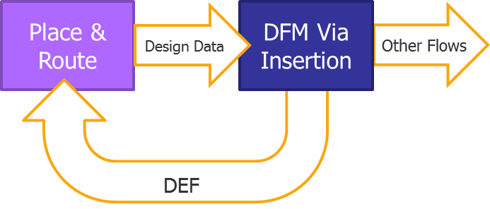
Figure 2. Back-annotating DFM enhancements to the P&R file helps designers minimize critical areas while ensuring that correct timing is preserved.
However, file translation can be a tedious process, and not everyone has the time or resources to build custom in-house solutions. CAD teams responsible for building and maintaining such solutions may need to support multiple design flows using tools from several vendors, which can further complicate implementation and support in production flows. An EDA solution that automates the translation process enables a faster and more uniform work flow across design teams, regardless of the design flows and tools they use.
For example, to make the back-annotation process simpler and faster for Calibre users, Mentor developed utilities that help designers automatically translate LEF/DEF data to GDS or OASIS formats, and back-annotate layer objects from GDS or OASIS to DEF. Applying these utilities to a multi-vendor flow for redundant via back-annotation simplifies the development of a flow that can connect with any P&R environment. Let’s walk through a demonstration of how the general process works.
Step 1: Read the DEF data
The Calibre fdi2gds and fdi2oasis utilities run as command line applications, but are also embedded in the Calibre reader, which enables the direct import of LEF/DEF objects and properties as annotated shapes on mapped layers. Designers simply set the Calibre input database system to LEF/DEF, and reference the design LEF and DEF data. Specifying net annotation during the LEF/DEF read automatically annotates DEF net names in the Calibre data.
Step 2: Generate redundant vias
Redundant via generation is executed with the Calibre YieldEnhancer tool or other Calibre flows. Based on technology-specific constraints, DRC-compliant locations for redundant vias and metal shapes are created on derived layers (Figure 3).
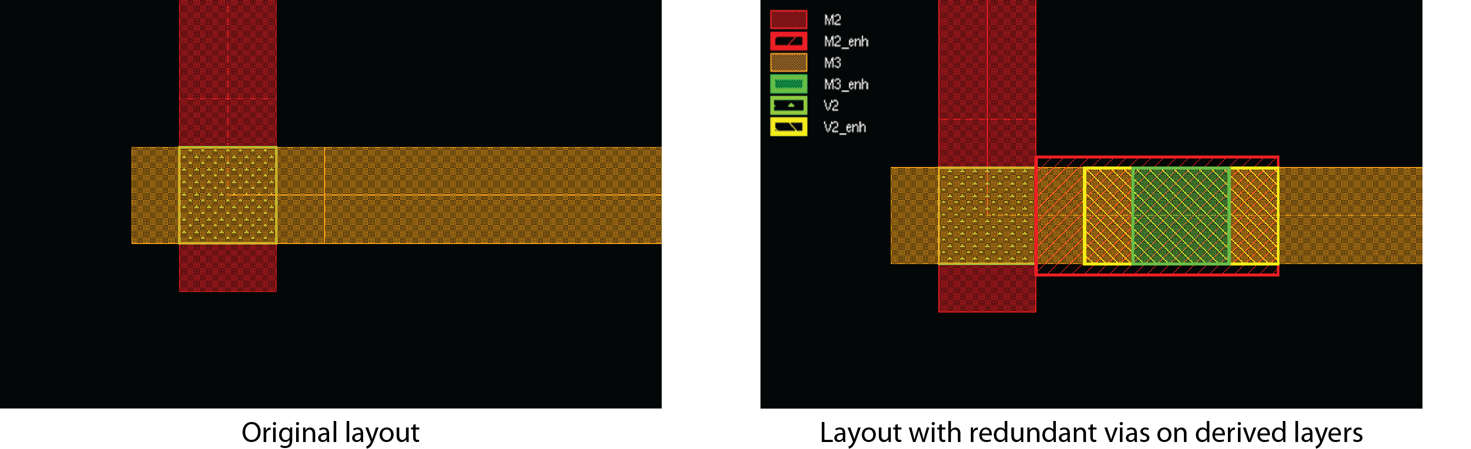
Figure 3. The DRC-compliant redundant vias are automatically generated in derived layers.
Step 3: Stamp objects
DEF net name properties on the input design shapes are used to establish net IDs. Connecting the original shapes to the derived enhancement shapes ensures they have the same net as the source data. Enhancement shapes are output to a DFM database with their net information.
Step 4: Back-annotate to DEF
The Calibre back-annotation utility (fdiBA) then automatically reads the enhancement shapes from the DFM database, and outputs the shapes into DEF format with the correct net information.
- MGC_CAL_1
+ RECT M3 ( -140 -70) ( 140 70)
+ RECT M2 ( -140 -86) (140 86)
+ RECT V2 ( -210 -70) ( 210 70) ;
Step 5: Import the DEF
Designers can now read in the exported DEF file to the P&R environment using native import DEF functions. Figure 4 shows a P&R layout after back-annotating DFM enhancements.
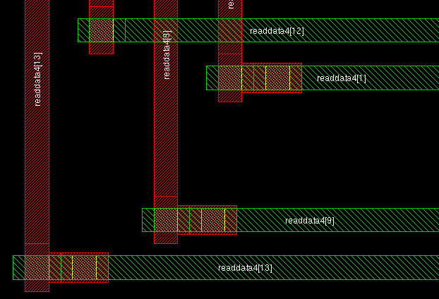
Figure 4. Back-annotated DFM enhancements in P&R layout
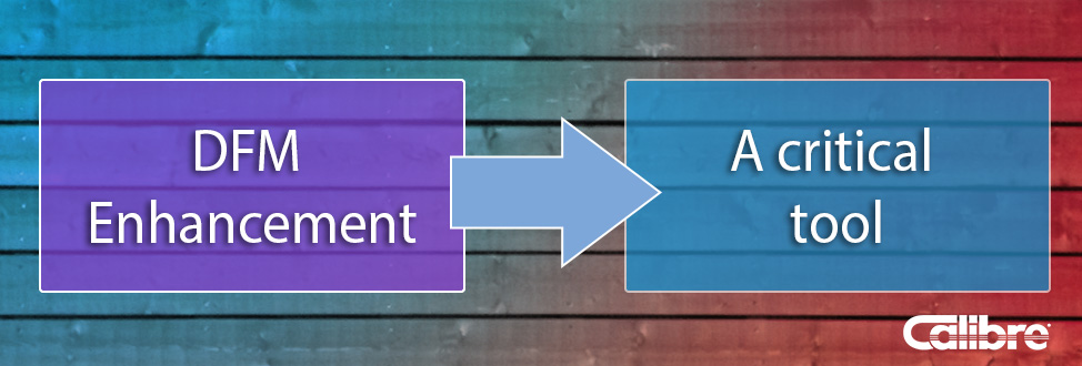
DFM enhancement is a critical tool for reducing manufacturing failures and improving yield. By enabling the automated back-annotation of DFM shapes and their associated information to P&R, file translation functionality can also help designers reduce iterations and close timing while ensuring the optimized design layout remains DRC-compliant.
Author
James Paris has supported Calibre design interfaces as a Technical Marketing Engineer with the Mentor Graphics Design to Silicon Division for more than 15 years. James holds a B.S. in Computer-Aided Design Engineering and an M.B.A. in Marketing.

Liked this article? Then try this –
White Paper: DFM Line-End Enhancement with Calibre Pattern Matching
This article was originally published on www.edn.com