Device Pin-Specific Property Extraction For Layout Simulation
By Phil Brooks, Mentor Graphics
Can you accurately extract device pin-specific properties without creating phantom nets?

As we work through the sub-20 nm design space, the interactions between and effects on devices that are near each other are becoming critical factors in achieving the desired electrical performance. Accurate extraction of device pin-specific properties for modelling these effects is essential to attaining design goals.
LVS extraction challenges
Layout vs. schematic (LVS) comparison tools provide a number of methods for gathering property information from a layout design database, and either using those properties for property verification during LVS comparison, or passing the properties to downstream tools for parasitic extraction and layout simulation analysis. Using these tools, however, can prove tricky when the properties being extracted require a high-level analysis of transistors and their surrounding nets.
Downstream tools that use the netlist produced by the LVS extraction run work best when nets and devices are represented with appropriate hierarchy. However, in sub-20 nm designs, full analysis of a layout frequently requires a flattened view of the transistors and nets to make appropriate calculations that consider surrounding layout and connectivity. When these flattened or partially-flattened netlists are sent to the LVS comparison process, or to downstream extraction and simulation tools, various errors can occur because the LVS and downstream tools do not see the nets and transistors in the hierarchy in which they expect to see them.
Separated properties representation
To solve the flattened netlist issue, many multi-vendor verification tool flows rely on a separate representation of layout device properties from the LVS device extraction, contained in a separate properties data file. A separate property data file allows cell-level representation of devices, while also enabling calculation of properties that are only meaningful at a block or full-chip level. Using this technique, property annotations are created at a high level in the design, while the layout netlist itself retains its hierarchical structure.
For example, consider the case of a simple circuit that has several placements of a subcell (Cell1) that contains a number of transistors.
.SUBCKT Cell1 1 7
M0 1 2 3 p
M1 3 4 5 p
M2 5 6 7
.ENDS
.SUBCKT TOP
X0 1 2 Cell1
X1 3 4 Cell1
.ENDS
With a separate property data file, this SPICE circuit hierarchical netlist can be annotated with a flat representation of properties that have different values for different instances of the design. In our example, the M1 device from Cell1 has consistent property values for the area of source (AS) and area of drain (AD) across both instances of Cell1. It is, therefore, represented only once inside the Cell1 structure. The other devices, due to the proximity of pin material outside of Cell1, have different values for each instance of Cell1. These varying device properties are represented in their promoted positions in the top-level cell. Here is the separate properties file written in a pseudo-SPICE format:
.SUBCKT Cell1
M1 AS=1.44 AD=1.47
.ENDS
.SUBCKT TOP
X0/M0 AS=1.67734 AD=1.75838
X0/M2 AS=1.64752 AD=1.45993
X1/M0 AS=1.27115 AD=1.75838
X1/M2 AS=1.43672 AD=1.39593
.ENDS
Post-device-extraction property calculation
This separate data format permits the formation of properties after the initial LVS device extraction processing takes place, which allows for an additional level of flexibility in the creation of properties for layout simulation flows:
- Examination of whole network device topology (e.g., properties that encode types of device parallelism in the layout),
- Faster performance of property analysis during the LVS extraction run,
- Better preservation of net hierarchy within the design,
- Attachment of source netlist device properties to layout devices based on LVS comparison’s matching of source and layout devices.
The common thread among the above requirements is that the devices must be fully recognized before the properties can be added. For example, attaching properties that encode device parallelism requires that the devices be fully recognized before their parallelism can be discovered.
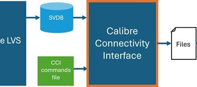
Various tool mechanisms can be used to perform net-level analysis. Ideally, a tool should have functionality that provides a variety of measurement and calculation methods used to attach numeric properties to polygons or directly logical nets. These properties, in turn, must be attached to specific pins on a device. Once these net properties are calculated, the separated properties file is used to pass these properties to downstream tools, and eventually to simulation.
However, when this net-level analysis requires promotion of a net upward in the cell hierarchy (for example, when analysis of a lower-level net requires examination of non-local design layers for proximity analysis), this process can create phantom nets. These phantom nets cause problems with downstream parasitic extraction tools, and avoiding their creation is a critical and tricky part of measuring these properties. Although these phantom nets occur when the nets are promoted into higher-level cells in the design for analysis context, the nets themselves don’t really need to be represented at that level.
The following describes an innovative process that enables high-level simulation analysis by attaching pin-specific properties to devices in a design, and annotating those properties back to devices in a way that does not create phantom nets in the design.
LVS device program
A typical LVS device extraction program allows device recognition and l, w property calculation for a P-type MOS device for which we want to extract the high-level pin properties before additional properties are added:
DEVICE MP PGATE PGATE(G) PAA(S) PAA(D) NTB_S(B) [
property w,l
w = perimeter_co(PGATE,PAA) * 0.5
l = perimeter_outside(PGATE,PAA) * 0.5
]
Separate property calculations
The next critical step requires a process for the direct calculation of separate properties (i.e., those properties not needed for LVS comparison) to be written to the separate property annotation file. To make this calculation, we must perform two discrete steps:
- Calculate a pin-specific property and associate it with the device pin shapes
- Transfer the property from the pin shape to a specific device formed by that pin
To demonstrate this process, we will use a very simple calculation—area of source and drain pins—but more complex pin-specific properties can be similarly calculated. To add the area of source and drain calculations to the device, we use a simple addition to the rule deck, as follows:
First, calculate the area of source and drain pins on the pin layer PAA:
PAA_p = PAA CALCULATE PROPERTY [ AREA = AREA(PAA) ]
Next, attach the AREA property to the device. Since there are multiple swappable pins being derived from the same layer, it is important here that the supplemental property device programming language have a mechanism for selecting among the pin shapes, so the appropriate property-annotated shape can be associated with the appropriate pin on the device:
ATTACH PROPERTIES TO DEVICE MP <PAA_p> [
PROPERTY as,ad
as = GET_PROPERTY_VALUE_BY_PIN ( PAA_p, AREA, s )
ad = GET_PROPERTY_VALUE_BY_PIN ( PAA_p, AREA, d )
]
The AS and AD properties could have been calculated in the main DEVICE program by simply using its built-in analysis functions, but there is a significant advantage to performing the calculation afterward using a separate mechanism. When the DEVICE programming block is used to calculate the pin-specific properties, some promotion may be necessary to resolve the property for a pin when that analysis extends out of a cell. If this promotion also causes the entire device and all of its nets to be promoted out of the cell, it may cause additional processing time, because the more complex full device recognition process happens on a flattened design. By using the post-processing approach, we avoid the device promotion, and accurately place the pin-specific properties on the devices after the fact.
Shorting analysis
Proper handling of our pin-specific property may also need to take into account whether or not the source and drain pins of the device are shorted. The challenge is to alter the property calculation based on the presence of a hard short. One common technique for handling AS and AD properties is to use an average value for both properties when shorting occurs. One approach to solving this problem is to compare pin net values inside the post-processing:
ATTACH PROPERTIES TO DEVICE MP <PAA_p> [
PROPERTY AS, AD
AS = GET_PROPERTY( PAA_p, AREA, s )
AD = GET_PROPERTY ( PAA_p, AREA, d )
if ( GET_PIN_NET(s) == GET_PIN_NET(d) ) {
AD = (AS+AD)/2
AS = AD
}
]
For AS and AD calculation, this approach works just fine, but in cases where more complex properties are being calculated that may require examination of non-local layers, the use of GET_PIN_NET will cause resolution of low-level nets in a cell at high levels in the design. This results in net promotion and the appearance of the dreaded phantom nets. To prevent these phantom nets, we avoid accessing the pin in the separate property programming block by keeping track of the fact that the device is shorted within the initial DEVICE program:
DEVICE MP PGATE PGATE PAA PAA NTB_S [
property w,l,shorted
w = perimeter_co(PGATE,PAA) * 0.5
l = perimeter_outside(PGATE,PAA) * 0.5
if ( GET_PIN_NET(s) == GET_PIN_NET(d) ) {
shorted = 1
} else {
shorted = 0
}
]
We can then use the value of the shorted property in the post-processing program, rather than directly accessing the net value.
ATTACH PROPERTIES TO DEVICE MP <PAA_p> [
PROPERTY as,ad
as = DFM_NUM_VAL( PAA_p, AREA, s )
ad = DFM_NUM_VAL( PAA_p, AREA, d )
if ( shorted ) {
ad = (as+ad)/2
as = ad
}
]
Ideally, the extra “shorted” property remains hidden from netlister and downstream tools.
More complex analysis of pin geometries and the upper-level nets to which they are attached can be handled using a similar process.
Conclusion
Pin-specific properties can help improve the accuracy of layout-based simulation results. Net-specific property calculation and device pin-specific property specification together provide a convenient way to calculate those properties and pass them through to downstream extraction tools and simulators.
Author
Phil Brooks is a senior software engineer in the Design to Silicon Division of Mentor Graphics, where he is the primary architect of the Calibre LVS product
This article was originally published on www.semiengineering.com