Best practice in scan pattern ordering for test and diagnosis
By Jay Jahangiri and Wu Yang, Mentor Graphics
By creating and applying scan patterns in the right order, you can save on scan test costs, reduce pattern set size, achieve goal coverage, and collect data for diagnosis.
Test engineers want to create and apply scan patterns in efficient sequences that detect the greatest number of defects and best diagnose the root causes of failures. The challenge lies in determining the ideal formula. A series of competing factors must be considered if you are to balance test cost, test quality, and data collection. Here, we describe some best practices that cover the creation and application of cost-effective pattern sets.
You certainly can improve defect detection and silicon quality by applying lots of patterns and pattern types (e.g., gate-exhaustive patterns), but this quickly becomes expensive. A cost-effective strategy targets the types of fault model that detect the largest number of silicon defects without leading to over-testing. You implement such a strategy by creating a sequence in which each pattern set can be fault simulated against other fault types before additional (or ‘top-up’) patterns are created to target remaining undetected faults.
Such ‘cross-fault simulation’ can greatly reduce test cost, but a question remains over the order in which patterns should be created. In general, you should prioritize the creation of patterns with the strictest detection requirements (e.g., path delay patterns). Figure 1 shows a typical pattern generation process.
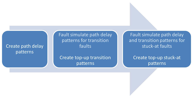
Figure 1. A typical scan pattern creation process (Mentor Graphics)
Test patterns fall into three main categories:
- Chain test patterns;
- At-speed patterns, including include transition, path delay, timing-aware, delay cell-aware, delay bridge, and delay functional User Defined Fault Modeling (UDFM) patterns*; and
- Static patterns, including stuck-at, toggle, static cell-aware, static bridge, and static functional UDFM patterns*.
You should use the ordered list of scan pattern types in Figure 2 as a guideline for creating and fault simulating each pattern type in order to achieve the smallest pattern set (at-speed patterns are shown in a darker shade).
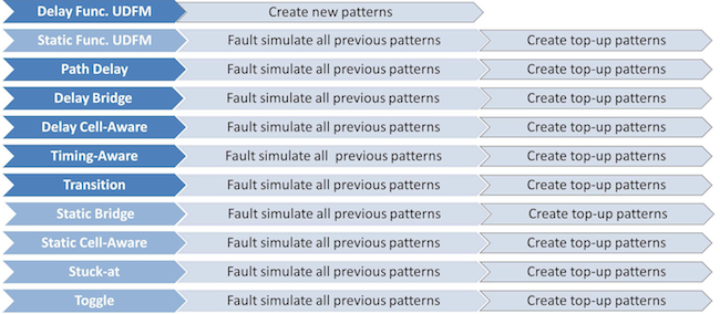
Figure 2. Scan pattern creation and fault simulation for the smallest pattern set (Mentor Graphics)
Before creating and simulating new patterns, all previously-created patterns should be simulated for the target fault type. As noted earlier, this is a key step toward ensuring that only those top-up patterns that target the remaining undetected faults need be created.
You can further optimize the pattern sets by examining field return and manufacturing yield data.
An important point is that the most efficient sequence for creating a pattern set is different from the ideal order in which sets should be applied to the tester. You should therefore save all pattern sets separately so that they can be applied on the tester according to the appropriate test phase and desired defect detection.
Determining scan pattern order during tester application
On the tester, the order in which different types of patterns are applied depends on whether you are running a ‘go/no go’ production test, which stops testing at the first failure, or a data-logging exercise, where information about some or all failures is needed for diagnosis.
If the goal is to determine quickly which devices failed without any failure data log, it is best to apply the chain patterns first, followed by the at-speed patterns at functional (specification) speed and then the static patterns.
Within an at-speed pattern set, we recommend applying patterns in the following order:
delay bridge —> delay cell-aware —> timing-aware —> transition —> path delay —> delay functional UDFM
We recommend this order for applying static patterns:
static bridge —> static cell-aware —> stuck-at —> static functional UDFM —> toggle
For logging failing data for volume diagnosis, we the recommend the flow in Figure 3.
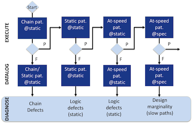
Figure 3: Scan pattern application order during yield ramp (Mentor Graphics)
The goal here is to ensure that diagnosis can have staged failure data for isolating different types of defects. We consider this flow in more detail in a separate whitepaper: Effective Ordering and Application of Scan Patterns for Cost, Quality, and Diagnosis Data Collection.
Conclusion
The ordering of test pattern types is different for pattern creation from tester application. Considering test coverage, pattern size and efforts in pattern creation, a best practice flow creates the most restrictive patterns first, fault simulates the remaining faults and creates top-up patterns if needed. During tester application, ‘go/no go’ test needs to have the most easily failed patterns to be run first, while testing to a data log for diagnosis needs the tests to be staged so that diagnosis can use them to isolate root causes among chain defects, static defects, and path-related defects.
Notes
* These are the design’s functional patterns described through User Defined Fault Modeling (UDFM) so that they can be applied easily through scan. This whitepaper provides more information on the technique.
Authors
Jay Jahangiri and Wu Yang are technical marketing engineers in Mentor Graphics’ silicon test division.

This article was originally published on www.techdesignforums.com