Manage Giga-Gate Testing Hierarchically
By Ron Press, Mentor Graphics
Reuse block test patterns at the top level to control test time and cost with hierarchical test

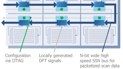
When designs get big, designers often implement hierarchical “divide and conquer” approaches through all phases and aspects of chip design, including the design-for-test (DFT). With hierarchical test, the DFT features and test patterns are completed on blocks are re-used at the top level. Hierarchical DFT is most useful for designs with 20 million gates or more, or when the same cores are used across multiple designs. The benefits of hierarchical test include reduction of test time, reduction of automatic test pattern generation (ATPG) run time, better management of design and integration tasks, and moving DFT insertion and pattern generation much earlier in the design process. Figure 1 depicts hierarchical test.
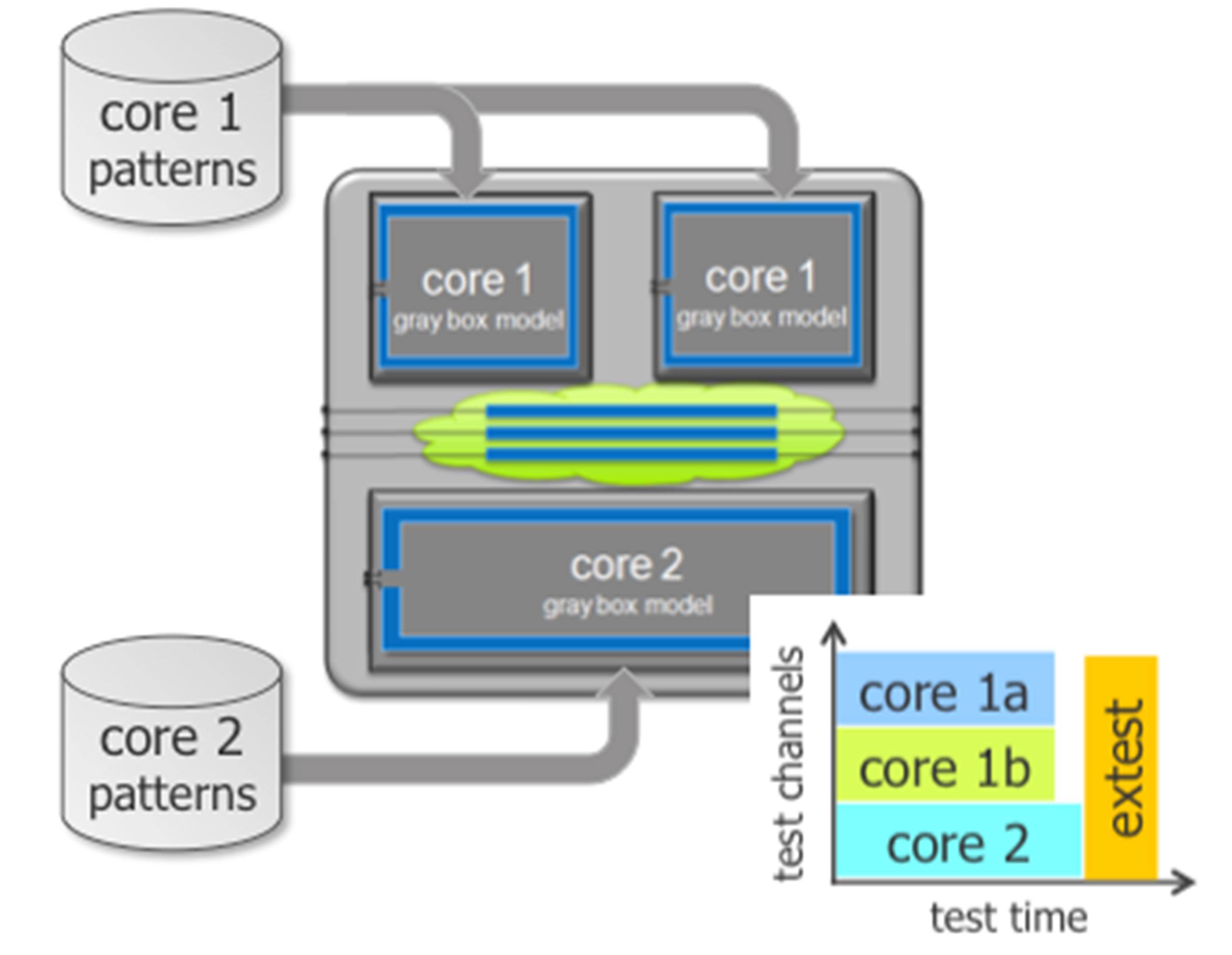
Figure 1. A conceptual drawing of hierarchical test.
Today’s hierarchical test methodologies are different from those used years ago. Hierarchical test used to mean just testing one block in the top-level design while all the other blocks are black-boxed. The block being tested is isolated with special wrapper scan chains added at the boundary. While this method improves the run time and workstation memory requirements, it still requires you to have a complete top-level netlist prior to creating patterns. Plus, patterns created previously cannot be easily combined with other similarly generated patterns in parallel; they are used exactly as they were constructed during ATPG (i.e. generated and applied from top level pins).
Fortunately, the automation around hierarchical test has significantly improved in recent years. There are significant advantages in managing design and integration tasks and design schedule, including:
- It moves DFT effort earlier in the design process because all the block DFT work and ATPG can be completed with only the block available; You don’t need to wait until the top-level design or test access mechanism (TAM) is complete.
- It helps with core reuse and use of 3rd party IP. Block-level patterns and design information are saved as plug-and-play pieces that can be reused in any design.
- It allows design teams in different locations to work on blocks without conflicts. A top-level design is never needed in order to generate the block-level patterns. Only block data is needed to verify that the block patterns can be effectively retargeted in the top-level design and that the top-level design can be initialized such that the block being tested is accessible.
- It simplifies the integration of cores at the top level. Various block patterns are generated independently for each different block, but if the top-level design enables access to multiple blocks in parallel, then the patterns can be merged together automatically when retargeting to the top-level design.
In addition to the design, integration, and schedule benefits of hierarchical test, it also reduces ATPG and workstation memory. Many people assume that top-level pattern generation for the entire chip in one ATPG run is more efficient for test time than testing blocks individually. In fact, hierarchical test is often 2-3x more efficient than top-level test. I’ll try to describe why with an example. Figure 2 shows two approaches to test an IC. For each block we maintain a 200x chain-to-channel ratio. Thus, in the top-level ATPG case 800 chains with 4 channels results in a 200x compression ratio. However, in the hierarchical case there are 12 channels available for each core, so to maintain 200x compression ratio we would have 2400 chains. These chains would be 1/3 the length of the chains in core 3 top-level ATPG.
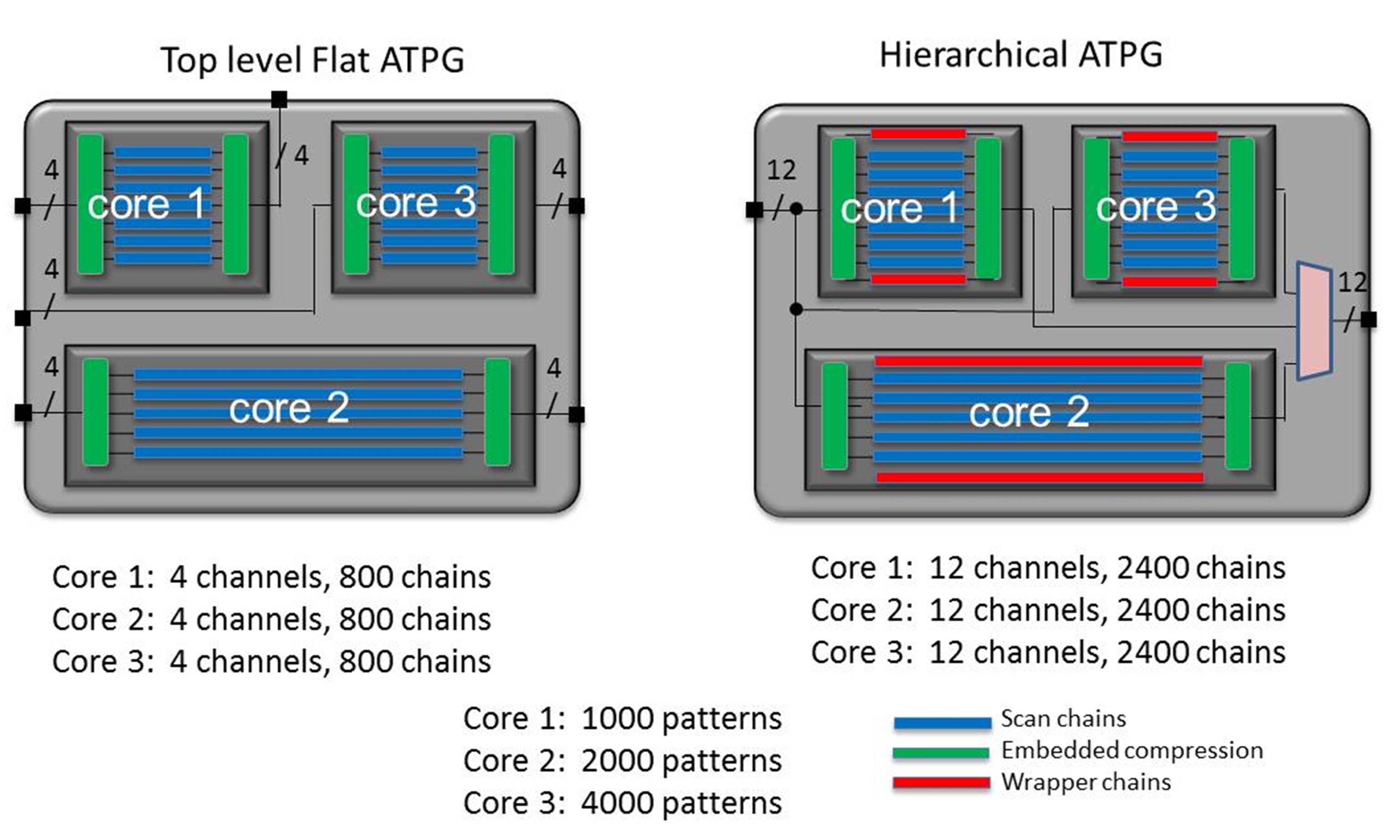
Figure 2. Flat ATPG tests all cores in parallel. In this case, core 1 requires fewer patterns than core 3. After 1000 patterns are applied, the four channels used for core 1 are useless bandwidth.
Top-level ATPG pattern count will be dictated by the block with the largest number of patterns. In this case, the tester cycles will be equal to
{(core 3 scan cells) / (800 chains)} * 4000 patterns
The hierarchical ATPG will run each block sequentially in this case. So each block can use all 12 channels and would have 2400 chains internally
{(core 1 scan cells)/ (2400 chains)} * 1000
+ {(core 2 cells)/ (2400 chains)} * 2000}
+ {(core 3 cells)/ (2400 chains)} *4000}
If each core has the same number of scan cells, then we get this comparison:
(scan cells)/800 * 4000= (scan cells) * 5 for flat ATPG
and (scan chain length) * {(1000/2400) + (2000/2400) + (4000/2400)}
= (scan chain length) * 2.9 patterns for hierarchical ATPG
So in this case, hierarchical test is 60% the test application time as flat ATPG.
In hierarchical ATPG, the bandwidth of all channels are used on one block at a time. Thus, more chains can be used on each block to maximize the channel bandwidth. This can significantly improve the efficiency of DFT. The impact can be more pronounced when different blocks require different pattern types.
Hierarchical DFT flow
The flow starts with core-level DFT, which includes insertion of scan chains, generation and insertion of compression IP, an adding wrapper chains to isolate cores. You can reuse existing function flops as shared wrapper cells and only use dedicated wrapper cells if absolutely necessary.
The next step is core pattern generation. Using ATPG software, you create the core-level test patterns and generate gray-box models. The gay-box models are light weight models for external test and pattern retargeting. You have some flexibility to preserve specific instances outside of what the automation might choose for you.
Pattern retargeting is next. You retarget the core-level patterns to the top level and can merge the pattern sets to create a “intest” pattern sets. The full netlist is not needed for pattern retargeting; just the top-level logic and core-level gray box models or even block box model with a “core description file” that provides information about the block level test structure.
After pattern retargeting, you create top-level interconnect tests. When making the top-level “extest” patterns, the full netlist never needs to be loaded into memory, just the top-level logic and core-level gray box models.
With some up-front design effort and planning, the biggest challenges of testing giga-gate SoCs can be addressed with a hierarchical DFT methodology.
Author
Ron Press is the technical marketing manager of the Silicon Test Solutions products at Mentor Graphics.

Liked this article? The try this –
White Paper: Divide and Conquer: Hierarchical DFT for SoC Designs
This article was originally published on www.semimd.com