Updating models in Solid Edge technical publications when CAD designs change

With Solid Edge technical publications solutions, designers can quickly create many types of technical documents—from simple illustrations for end user manuals to interactive 3D technical documents for manufacturing and service.
But designers ask us the same question a lot: what if my model changes? Do I need to start from scratch in Solid Edge? The short answer: No, Solid Edge has built-in functionality to handle downstream changes to your designs with ease.
Using the Update capability in Solid Edge
With the Update capability in Solid Edge technical publications, you can start document creation while designing the product. If the model changes, you can update it inside Solid Edge technical publication with a single click.

Generally, it’s best to use the default option when updating document or illustration sets with a revised 3D model. However, in some cases it can be useful to modify these settings. The options available for updating are listed and defined in table below.
| Option | Description |
|---|---|
| Maintain Material | When checked, does not replace material changes from the incoming model |
| Update Thumbnails after Update | Not generally necessary; when checked, forces all illustration thumbnails to update |
| Delete Original Model before Update | Not generally necessary; may be useful for very large models |
| Use Displayed Part Name (DWF Only) | May be useful when updating old files where the original model was DWF and matching part names |
| Match parts by name only | Default setting will only match parts based on the name of the part in the CAD; consistently matches parts because matching is based on an absolute and easily compared name; will update modified parts |
| March parts by location | Optional setting; the software will attempt to match parts based on location within the model, and will attempt to identify matches; useful for replacement parts |
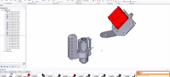
After an update, you will see a new option in the Model tree that displays the new parts that were added to the model on update. This can be used to easily find, toggle selection, and toggle visibility to make manual changes to illustrations when an update includes new parts or replacement parts. If parts were simply modified (not added), they will not show up in the model tree.

Furthermore, exploded views may indicate missing parts by color-coding the step in the exploded step tree. In this case, you can quickly edit the step and add the missing part, if needed.

The update process in Solid Edge is seamless and allows you to create manuals before a design is finalized. You no longer have to worry about re-doing manuals when the design changes.
For a complete walkthrough of the update process, watch the video below.
Experience the power of Solid Edge technical publications solutions
Solid Edge helps engineers and designers around the world bring new products to market with affordable, easy-to-use software solutions that address all aspects of the product development process – 3D design, simulation, manufacturing, data management, and more. Solid Edge combines the speed and simplicity of direct modeling with the flexibility and control of parametric design – made possible with synchronous technology.
Solid Edge technical publications solutions are closely integrated with Solid Edge, allowing you to work directly with your Solid Edge parts and assemblies, and eliminating the need to convert your CAD files to a different format. And changes to the original design are easily incorporated into existing documents, speeding the engineering change process and ensuring that published documents reflect the current design. Try Solid Edge for free →


Comments