What’s new in Simcenter FLOEFD 2506? | CAD-embedded CFD simulation
The new Simcenter FLOEFD 2506 software release is now available in all its CAD-embedded CFD variants, and also the Simcenter 3D embedded version. This release delivers focused improvements for electronics thermal design workflows based on user feedback, so please read on below in full to explore every new feature, or scan the topic areas on the left to shortcut to the sections that interest you.
Model the complexity

Controlling sub-models: Project parameters from components
Many Simcenter FLOEFD users work with sub models. Simcenter FLOEFD 2506 delivers an advantage to define project parameters in sub projects that can now propagate upward into your main CFD model for easy use.
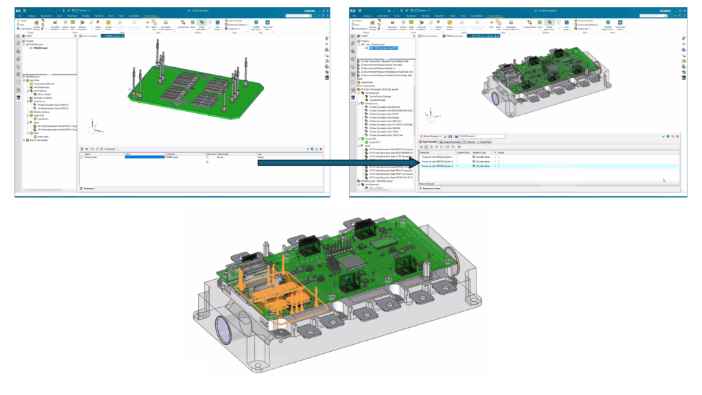
Crucially, this also helps in simplifying the creation of elaborate electronics thermal component models for inclusion in libraries and for wider re-use of sub models. The following video demonstrates the steps involved for a power module example of how parameters transfer from sub project to main project
Improving reduced order modeling
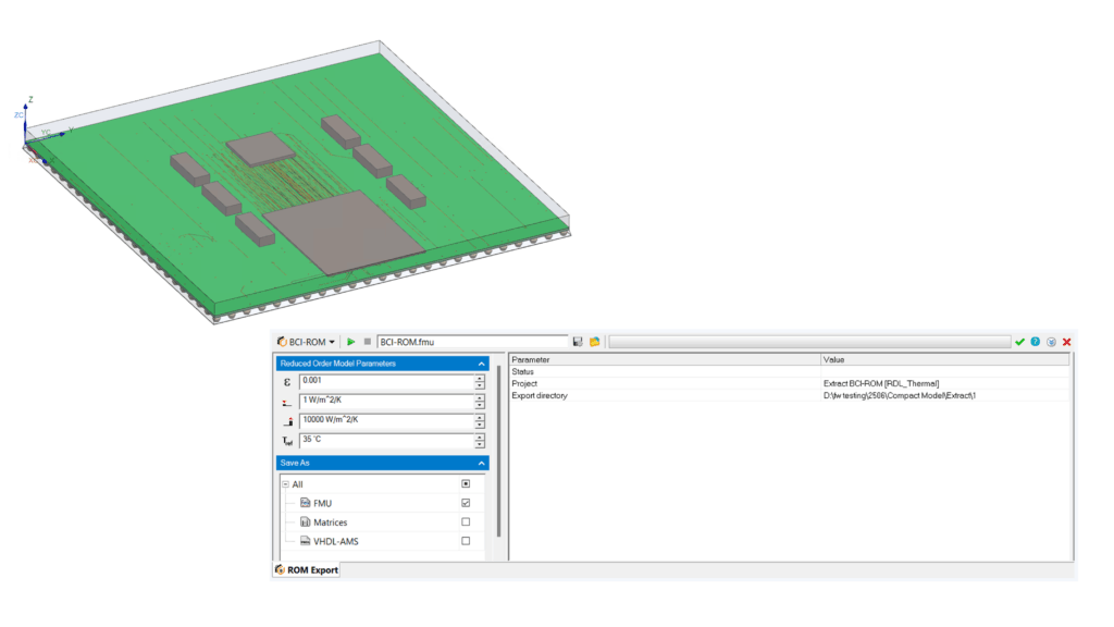
BCI-ROM creation supports models including a Smart PCB
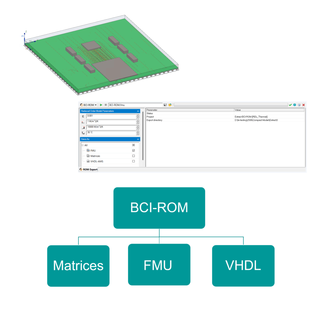
BCI-ROM reduced order thermal model generation was introduced in Simcenter FLOEFD back in version 2020.1 and since then have been successively enhanced. Simcenter FLOEFD’s Smart PCB offers a computationally efficient network assembly based approach that is accurate for modeling the detailed material distribution in complex multi-layer PCBs. Users can now generate a BCI-ROM in various formats (matrices, VHDL-AMS, FMU) from a 3D conduction-only thermal model containing a Smart PCB.
A BCI-ROM can be extracted from a Simcenter FLOEFD project using Fine or Averaging Smart PCB settings.
As a reminder, you can read about applications of 2 BCI-ROM formats in these 2 past blogs for system simulation and circuit simulation:
Thermal management of Electric Vehicles is a breeze (FMU format BCI-ROMs)
Frontloading electrical circuit analysis with thermal models (VHD-AMS format BCI-ROMs)
FMU based components – using reduced order thermal models in CFD more easily
You can now use and manage multiple FMU based components in projects and sub projects far more easily, and these sub components can be added to libraries. This new capability is called “FMU as a feature”.
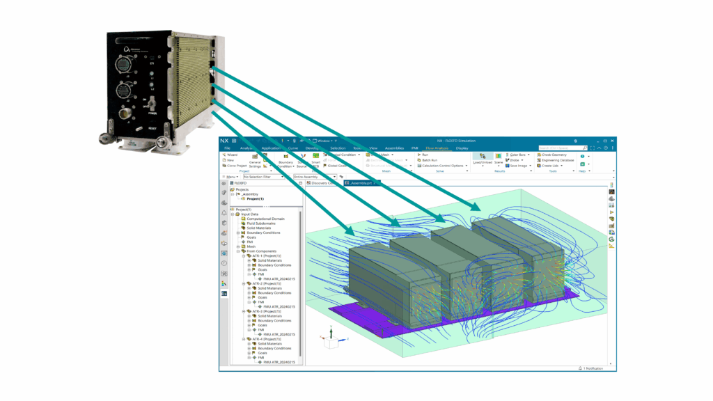
The key value for users is being able to see all the parameters, including inputs, for an FMU based component in one dialog. This is clearer and more intuitive, especially when you are using multiple FMUs in a larger main model.
Multiple FMUs can be managed in your main project, or added from sub projects using “add from component, or stored in your library as a compact model.
[FMI and FMU notes: Simcenter FLOEFD has had FMI standard support for co-simulation and selected use of FMU models since version 2019.4 and export functionality for BCI-ROMs in FMU format since version 2020.2]
BCI-ROM: average and maximum temperature prediction
Insights into average and maximum temperature provide insights into energy stored or dissipated for a component or sub model created as a BCI-ROM. In the past, when setting up a BCI-ROM, the author producing the BCI-ROM had to specify points goals for all bodies of interest before generating it and consider location and attendant naming of these to identify them. The benefit of having volumetric goals that can be configured within a BCI-ROM means average and maximum temperatures are easily reported. The author can save time in set up and the consumer of the BCI-ROM does not need to consider location of multiple temperature values to calculate the average temperature and maximum temperature.
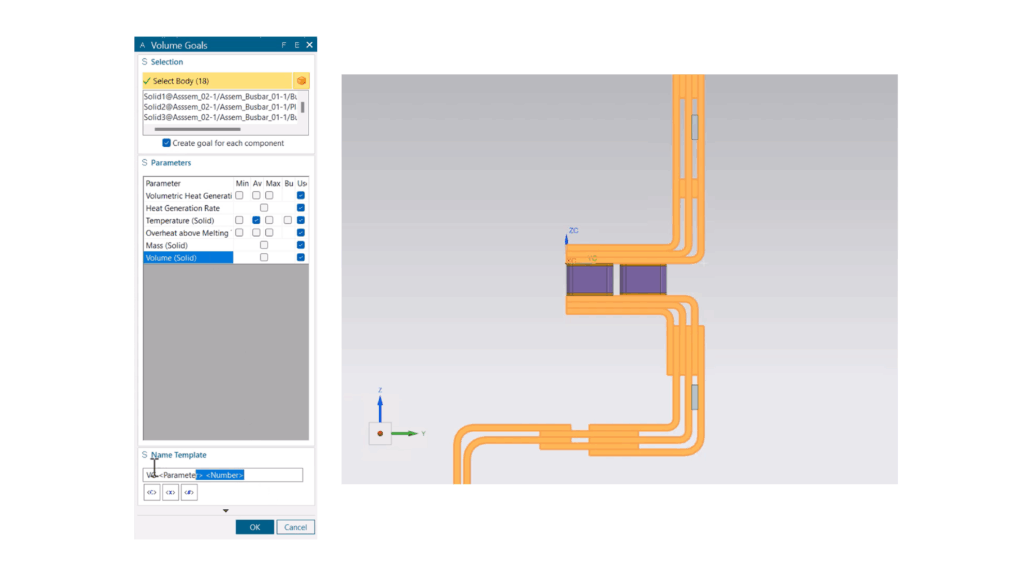
This is particularly useful for applications such as modeling a bus bar that may consist of multiple bodies that are not easy to predict location of max. temperature in advance due to their shape or multiple parts. Watch this video for a demonstration of the steps involved to outputting maximum and average temperature for arbitrary geometry.
Structural analysis – Transient simulation and transient explorer
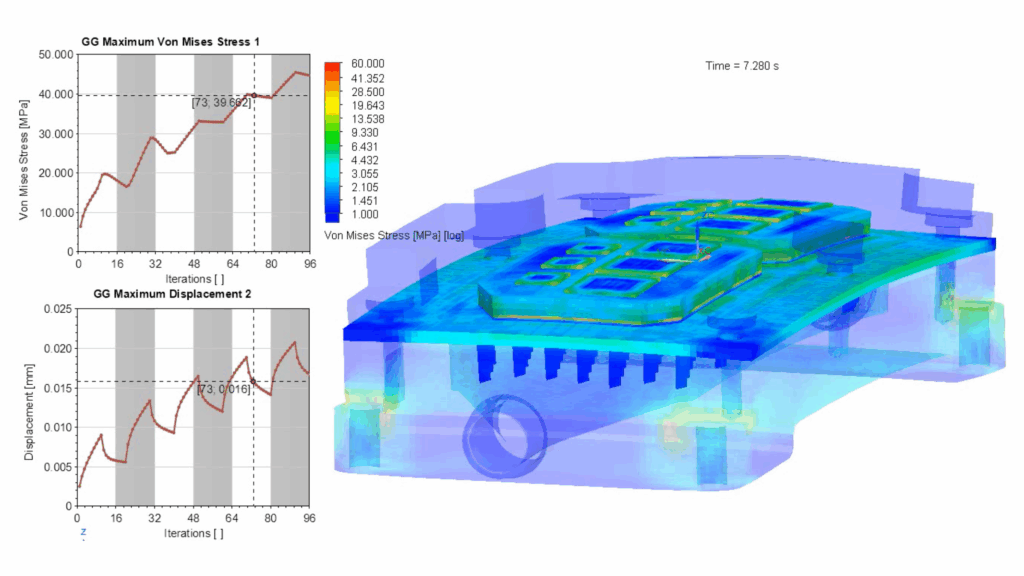
Coupled fluid, thermal and structural unsteady analysis and results post-processing is advantageous for many electronics thermal applications. This has been highly requested since the release of Simcenter FLOEFD’s structural capabilities aimed at thermo-mechanical stress analysis tasks for electronics thermal design.
Users can now perform a fit for purpose co-simulation using Simcenter FLOEFD’s fluid and thermal solver in conjunction with Simcenter NASTRAN non-linear 401 solver. This brings the benefits of combined transient analysis into a single Simcenter FLOEFD project. Timelines of analysis in the different solvers are synchronized in a linkage whereby unsteady pressure and temperature fields obtained as a result of CFD thermal analysis are interpolated in time with structural analysis. Transient Explorer is then used to review results as graphics plots and goal charts.
Notes:
- Co-simulation between Simcenter FLOEFD’s fluid and thermal solution with Simcenter NASTRAN non-linear 401 solvers does not support FSI and dynamics phenomena at this time.
- Linear structural analysis using Simcenter FLOEFD structural analysis capabilities with unsteady fluids and thermal analysis is also possible in a single project now instead of requiring separate projects.
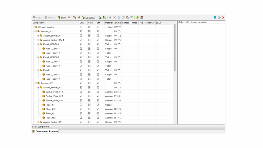
Component Explorer – status and temperature column
The Simcenter FLOEFD 2506 release introduces functionality so you can control component status and associated features more easily, all within the same dialog. This means you can easily suppress aspects of your model assembly quickly by selecting if they are modeled via selection of a check box for the analysis type or removing material and volume details in the columns within the Component Explorer viewing window.
To retrieve all temperatures of components within your simulation model for steady state analyses in a tabular format is advantageous. You can now see a table and export it to Microsoft Excel using Component Explorer as a column with final average temperature values has been added. So you can export temperatures vs component names using Batch results processing.
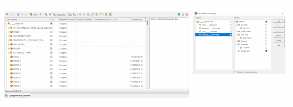
Below is a video of the steps to exporting all temperatures to Microsoft Excel
Explore the possibilities
Automation enhancements in EFDAPI
EDFAPI, the new API, introduced back in Simcenter FLOEFD 2312 continues to be developed based on user feedback. Supporting PYTHON scripting as of Simcenter FLOEFD 2412, the latest Simcenter FLOEFD 2506 release introduces 2 new enhancements:
Face selection using normal direction
Consider an example PCB thermal analysis case where you want to automate tasks such as creating 2R models from an array of components on a board. You can now do the automated selection of top face of 2R components more easily as it is much easier to select face by normal vector. The Normal vector is specified in the local coordinate system, so it is straightforward to use coordinate values.
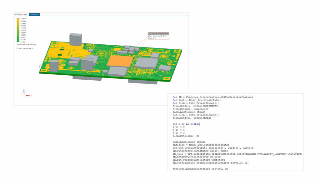
Below is an overview in a short video of what the commands look like in practice:
Access geometry parameters:
For geometry that is parameterized you can now control it through EFDAPI and scripting. This enables you to improve automation for optimization purposes and for improved connectivity of Simcenter FLOEFD with external optimizers.
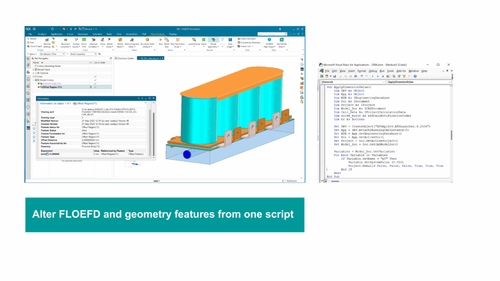
This is available in the majority of the CAD variants of Simcenter FLOEFD*. You can combine this with any parameters you can control with the parametric study tool. For example, if you have set up parameters as calculations in Simcenter FLOEFD for NX, using synchronous technology, then you can access these via scripting now.
*This feature is not available in Simcenter FLOEFD for CATIA variant at this release
Go Faster
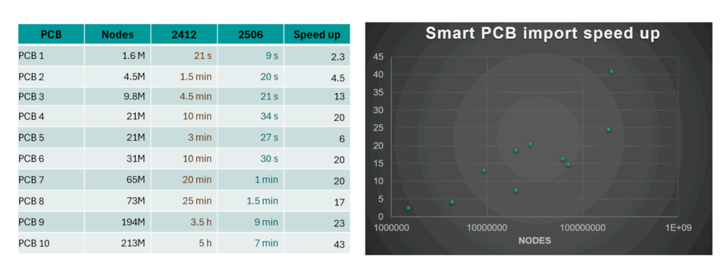
PCB thermal analysis: Smart PCB import speed – up to 40x faster
This release delivers a very significant speed increase in the import of complex large PCB files created as Smart PCBs i.e the transfer time to import a Smart PCB model from the EDA Bridge utility. For among 10 example cases of PCB investigated – indicative speed up is in the range of 2 to 20 times faster for a mid-sized PCBs and for a large complex boards 20 to over 40x times faster. This is of particular value when importing EDA data for very large boards.
As a reminder: A Smart PCB is a computationally efficient modeling approach to modeling the layers and copper in a board as a network assembly.
Taking a look at the speed up in terms of node counts as a given metric of PCB complexity and the mode used being “fine”, with 300 tiles along the longest PCB side, the following table and chart shows the range of speed up for import from the 10 example boards investigated.
Assess PCB design modification faster: EDA Bridge Place Library Component
Appropriate component modeling fidelity vs available information at the design stage is a constant tradeoff for thermal engineers in electronic thermal management. Often thermal engineers and designers want to move ahead with design exploration tasks such as sizing heat sinks or critical component placement options on a board for early-stage design thermal purposes. If you have component thermal models in your library that can be used, you can now place these manually while using EDA Bridge utility in 2 ways:
- Drag and drop from the component library window list of components
- Click “place selected” – which places a component at the origin to then manually move
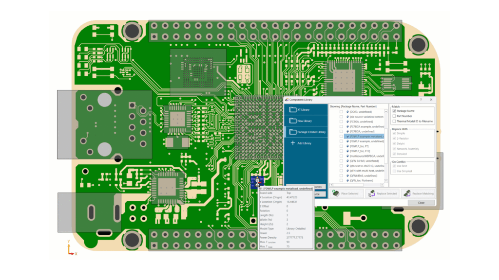
You can also automate this as the functionality is supported by scripting.
Stay Integrated
Component modeling and libraries: XTXML export enables editing
In Simcenter FLOEFD 2506 users now can export models in XTXML format, with a focus on features relevant to components (IC Packages). This allows users to import models from Simcenter FLOEFD Package Creator and make adjustments to the models (add geometry, update material properties, …) and then save the models in XTXML format. You can also export a manually created detailed model in XTXML format now.

Converting PDML into XTXML is also now possible through a Simcenter FLOEFD project and then to subsequently use it in component replacement tasks. The following video explains steps to exporting in XTXML format in Simcenter FLOEFD:
This builds on Simcenter FLOEFD 2412, when the ability to have libraries in EDA Bridge was introduced, and enabled you to to replace components while importing EDA data.
Where to download Simcenter FLOEFD 2506:
For current customers – please visit support center or click on one of the links below.
- Simcenter FLOEFD for NX 2506
- Simcenter FLOEFD for Solid Edge 2506
- Simcenter FLOEFD for CATIA V5 2506
- Simcenter FLOEFD for Creo 2506
- Simcenter FLOEFD SC 2506 (Simcenter FLOEFD for Simcenter 3D)
- Simcenter FLOEFD Standalone 2506
Other resources & upcoming webinars
- Don’t miss the July 10, 2025 live webinar ” Multiphysics design optimization of a power module cooling solution” – Registration link
- Listen in to a design engineer’s perspective on using Simcenter FLOEFD for valve design in this recent on-demand webinar “Frontloaded CFD” with a guest technical speaker from Alfa Laval – viewing link