What’s new in Simcenter FLOEFD 2205?
In this blog, please explore key enhancements in Simcenter FLOEFD 2205 release new in June 2022. Highlights include:
– Faster CFD meshing and handling of complex or low quality CAD Geometry
– Xcelerator Share – Cloud based engineering collaboration support
– Enhanced 1D Elements help speed up analysis in 3D CFD
– Improvements to PCB thermal analysis fidelity options and EDA Bridge workflow
– multi-physics capabilities in structural analysis and more…

Go Faster

Faster CFD meshing and handling of complex or low quality CAD Geometry
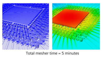
A new “Mesh Boolean” technology enables you to handle complex and extremely bad CAD geometry even faster and easier than before. When CAD Boolean cannot conduct Boolean operations successfully because of bad or dirty geometry (bad topology with missing entities, self-intersecting faces, etc.), the Mesh Boolean option can be used.

Mesh Boolean first meshes bodies separately and then conducts Boolean operations of the meshed bodies without using any CAD Boolean operations. This technology can prepare and mesh, even very dirty models, 5-15 times faster and easier without any user prior adjustments or healing of the model, i.e., automatically.
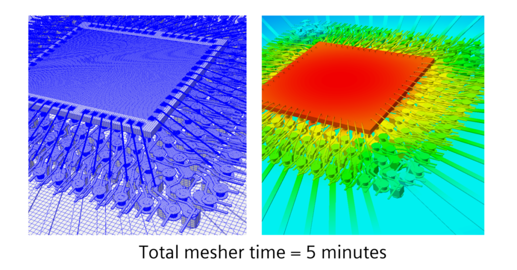
In previous versions “CAD Boolean” is the default option. “Preprocessor Boolean” is FLOEFD’s Boolean approach activated with “Improved Geometry Handling”. The new Mesh Boolean technology can be used together with the CAD Boolean diagnostic, combining the power of Mesh Boolean and the convenience of getting additional information, such as a diagnostic of the fluid domain. If the CAD Boolean diagnostic fails to detect the fluid domain, you still can proceed and mesh the model with Mesh Boolean. In that case additional subdomain diagnostics will be displayed in the Solver Monitor dialog. You are free to choose the default way of handling the geometry (CAD Boolean, Preprocessor Boolean (formerly called “Improved Geometry Handling” mode) or Mesh Boolean, as well as you can disable the CAD Boolean diagnostics
1D Elements in 3D CFD – speed up simulation with multiple chains
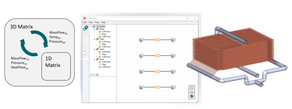
1D Elements were introduced in Simcenter FLOEFD 2021.2.1. These allow you to simulate a pipe with a 1D solver. You can convert a pipe into a chain of 1D Elements and solve their fluid and thermal interactions using 1D CFD embedded in 3D CFD Simcenter FLOEFD. This allows you to increase simulation speed and reduce mesh requirements. The 1D Elements feature doesn’t require any module or additional license and now you can create multiple chains with this release. Take a look back at this blog that introduced 1D elements for introductory information and a video.


Stay Integrated

Cloud based collaboration: Simcenter FLOEFD with Xcelerator Share
Xcelerator Share is a cloud-based collaboration service that supports distributed working environments and is available with many Siemens software subscriptions. It is part of the Xcelerator Portfolio and provides:
- Secure cloud storage with desktop syncing
- Permission-based project sharing with task management
- Engineering-centric view & markup
- Any device, any time, browser-based access to data
Xcelerator Share is now supported by Simcenter FLOEFD 2205. Leveraging Xcelerator Share allows you to set up collaboration projects, synchronize files to cloud storage directly from Simcenter FLOEFD running on your desktop, send messages and receive notifications, and also review and mark up documents. This supports more easily working with engineering colleagues in different departments, different locations and even with external suppliers and consultants.
Find out more in this example video below showing a project to improve a heatsink design in a liquid cooled power electronics IGBT module.

CGNS (CFD General Notation System) Export
You can export static and transient results into CGNS format in two ways: CGNS file is created by Simcenter FLOEFD or the CGNS file is created by another tool, imported into Simcenter FLOEFD and Simcenter FLOEFD outputs results values into the originally created CGNS file. The latter approach is recommended. For example, you can use CGNS export for acoustic analysis in Simcenter 3D based on FLOEFD field distribution. More about CGNS: CFD General Notation System (cgns.github.io).

Model the complexity

Electronics cooling – PCB thermal analysis and workflow enhancements

EDA Bridge related enhancements
PCB Localized Copper Modeling – Layered (Detailed) Thermal Territories
Layered (Detailed) Thermal Territories. A Thermal Territory around a package can now be represented in Layered (formerly called Detailed) mode in addition to the already existing Explicit Thermal Territory Type.
Layered Thermal Territories Provides an accuracy to account for the local variation of copper below a component. In Layered mode each layer is given an effective thermal conductivity. Suggested use is with footprint components such as simple, 2R and Delphi component thermal representations. Thermal properties can be calculated for each layer based on the copper in imported boards or set by the user.

You can easily define precedence of the overlapped Thermal Territories, so the territory with higher precedence will be applied in the overlapping region.
Smart PCB – Via Filler and Pin Filler Material definition
You can set material for Via Filler and Pin Filler in Explicity and Layered (Detailed) in Explicity or Layered mode. Currently you can define up to 4 different materials for Explicit or Layered modes. In Smart PCB mode, filler materials and via and pin groups can be adjusted after importing and the number of materials is not limited.
Smart PCB Solder mask support
You can add solder mask as solder top (smt) and solder bottom (smb) layers. You can define solder mask thickness and material. In the Smart PCB mode additional bodies are created for solder mask, please check the thickness of solder mass in advance. You can choose to add solder mask or not in the Model Summary dialog upon transferring.
Smart PCB Via Plating direction – In/Out
For a via group with plating you can now define whether the obtained via diameter is the hole diameter before plating (so the final hole diameter after plating will be smaller for the double thickness of plating) or after the plating (so the obtained diameter is the final hole diameter after plating).
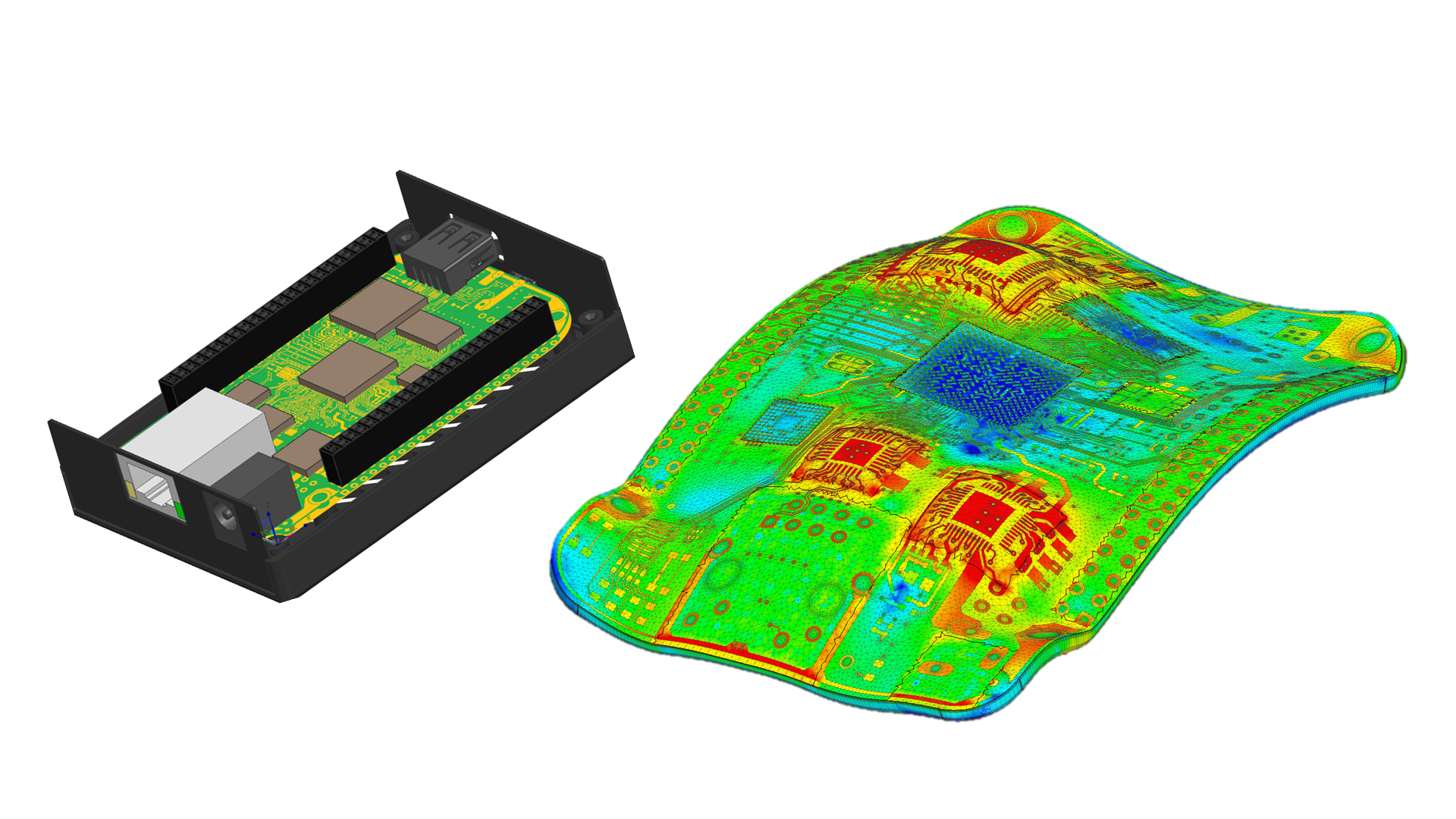
Smart PCB Thermo-mechanical analysis memory requirements reduction
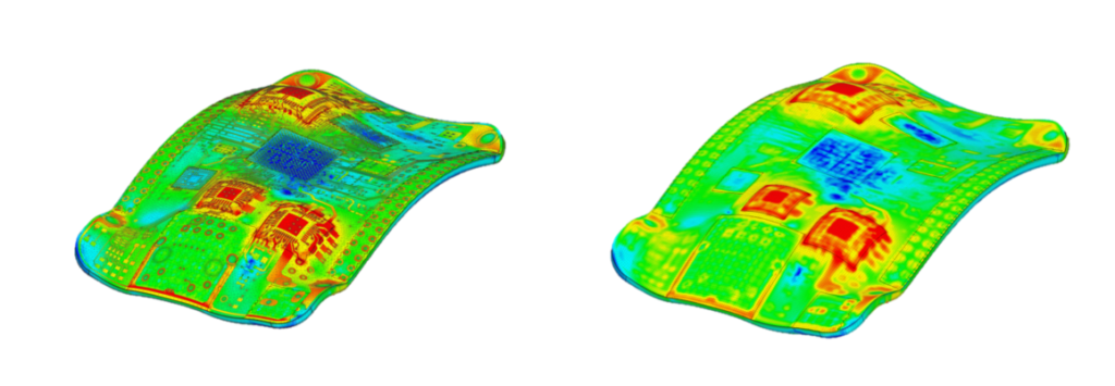
For Smart PCB Structural analysis, the memory requirement for PCB homogenization has been significantly reduced by 2 to 30 times. The homogenization mesher and solver was further accelerated. This allows making structural simulations of extremely large and complex PCBs on desktop computers feasible. For more information on PCB homogenization please read more in the Simcenter FLOEFD 2021.3 blog.
New structural analysis enhancements

A new type of contact allows simulating loosening contact (in terms of linear approach): if the gap width between bodies is much less than the element size then the contact is treated as a “Sliding” contact in the portion of the contact area where surfaces are pressed together. Otherwise, the contact is not applied and the bodies are disconnected. The originally non-deformed surfaces in contact must coincide or overlap to let Simcenter FLOEFD find the contact area using Boolean operations. Please use “Specific Force” postprocessor parameters or its components to locate resulting contact area

There are many more enhancements in Simcenter FLOEFD 2205 that can be explored in the release highlights document on Support Center for clients. These include incremental topics such as new Goals e.g Total Energy Balance, Volumetric Heat Generation Rate, Mass of solid and more through to improved visualization of Films on angled surfaces.
Resources: Download Simcenter FLOEFD 2205 Now
For Clients from Support Center:

Recent Simcenter FLOEFD Resources available to everyone online:
Webinar: Accelerate semiconductor package thermal design productivity with model-based systems engineering
(relevant to HDAP high density semiconductor package design worfklows)
On Demand Webinar: Thermal analysis of complex multi-layer printed circuit boards
On-Demand Webinar: PCB electrothermal modeling and thermo-mechanical analysis workflow
Blog: Reduced order thermal models from 3D CFD frontloaded into circuit simulation
