Simcenter Feko: Milestones in FEKO history – Part 1: The early years (1991–2013)
For more than three decades, the electromagnetic simulation software now known as Simcenter Feko has evolved from an academic research project into a leading solution used across a wide range of industries and applications. Originally developed as FEKO, the software became Altair Feko following Altair’s acquisition of EM Software & Systems in 2014, and later Simcenter Feko following Siemens’ acquisition of Altair in 2025. Along the way, advances in numerical methods, solver hybridization and computational performance have continuously expanded the scale and complexity of electromagnetic problems that engineers can address.
In this first part of the story, we look back at the early years from 1991 to 2013, exploring its academic origins, commercialization and the key technological milestones that shaped its development. Throughout this article, we use the original name FEKO to reflect the product’s historical identity during this period.

The academic origins of FEKO
The story of FEKO began in 1991 with the Master’s thesis of Ulrich Jakobus at the Institute of Radio Frequency Technology (IHF) at the University of Stuttgart. As part of his thesis, he developed a Method of Moments (MoM)-based code for electromagnetic field computation and named it FEKO, derived from the German phrase Feldberechnung bei Körpern beliebiger Oberfläche — field computations involving bodies of arbitrary shape.

In his subsequent PhD thesis, “Erweiterte Momentenmethode zur Behandlung kompliziert aufgebauter und elektrisch großer elektromagnetischer Streuprobleme,” Jakobus extended the approach by hybridizing MoM with asymptotic methods such as Physical Optics (PO) and the Unified Theory of Diffraction (UTD). These developments enabled the simulation of increasingly complex electromagnetic problems and the creation of digital prototypes for a variety of antenna configurations.

During this time, mobile telephony and automotive radio applications became increasingly widespread, driving growing industrial demand for electromagnetic simulation. Automotive OEMs began using FEKO to analyze antenna performance and electromagnetic compatibility (EMC).
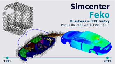
The pictures show early simulation results shared by Hirschmann Car Communication GmbH. The FM-antenna in the trunk lid of a convertible was solved with MoM already in 1997! The GSM antenna example in the rear screen of a sedan is even more impressive. At this higher frequency of 947.5 MHz a finer mesh (with edge length around 30 mm) is required. In 1998 this was practically unsolvable with MoM, but simulation engineers Markus Pfletschinger and Peter Riedhofer at Hirschmann Car Communication GmbH found a way of solving it using the more efficient hybrid MoM-PO approach. The antenna and nearby metallic parts are modeled using a full-wave MoM solver, while the rest of the car is modeled using Physical Optics (PO).

FEKO goes South African
As industrial demand for electromagnetic simulation continued to grow, FEKO needed to make the transition from an academic research code to a commercial software product. Ulrich Jakobus therefore teamed up with the South African startup EM Software & Systems (EMSS) in Stellenbosch to further develop FEKO for industrial applications.
The proximity to the renowned Department of Electrical and Electronic Engineering at Stellenbosch University provided access to highly qualified engineers and researchers, helping the young team grow. The first FEKO version developed and published by EMSS was released at the end of 1996.
FEKO made its first commercial exhibition appearance in 1998. The photo below shows Ulrich Jakobus and Gronum Smith presenting FEKO at the Applied Computational Electromagnetics Society (ACES) Conference in Monterey, California.

Numerical dosimetry for mobile phone emissions
With the growing popularity of GSM mobile communications in the late 1990s, concerns about human exposure to electromagnetic fields also increased. Evaluating typical exposure scenarios became increasingly important, while physical testing with human phantoms remained costly and time-consuming. Numerical simulation offered an efficient alternative.
To address this need, EMSS introduced capabilities in FEKO for evaluating the Specific Absorption Rate (SAR) in human-body models. SAR is a key quantity used to assess radio-frequency energy absorption in tissue and is referenced in exposure guidelines such as those from the International Commission on Non-Ionizing Radiation Protection (ICNIRP).
FEKO also supported peak-SAR evaluation, using an internal optimization process to identify the region of tissue with the highest average absorption over a specified mass, typically 1 g or 10 g. These capabilities enabled engineers to investigate mobile-phone exposure scenarios numerically and represented an early expansion of FEKO into electromagnetic safety and numerical dosimetry applications.

A revolution in electromagnetic simulation: MLFMM
At the beginning of the 21st century, electromagnetic applications expanded significantly, along with the frequency ranges that needed to be simulated. For traditional automotive FM antennas, one of the main automotive antenna applications in the 1990s, a vehicle was still electrically relatively small, and the Method of Moments (MoM) provided an effective solution. With the emergence of higher-frequency applications such as keyless entry systems around 434 MHz and GSM around 900 MHz, however, vehicles became electrically much larger relative to the wavelength.
This presented a major computational challenge. For conventional MoM, memory requirements grow approximately quadratically with the number of unknowns, making the simulation of increasingly large and detailed models computationally demanding.
The young EMSS team addressed this challenge by introducing the Multilevel Fast Multipole Method (MLFMM) in FEKO. MLFMM organizes interactions between different regions of a model hierarchically and separates near-field and far-field interactions. Through aggregation, translation and disaggregation operations, the method significantly reduces the computational resources required for electrically large problems. In particular, it improves the memory scaling from approximately N² for conventional MoM toward N log(N). FEKO was the first commercial electromagnetic solver to adopt this approach.
The introduction of MLFMM was a breakthrough for many FEKO applications, combining full-wave accuracy with much greater computational efficiency for electrically large models. In the years that followed, the method was extensively used in the automotive industry for antenna integration across a growing range of wireless services, including TV, GSM, GNSS, UMTS, LTE, Bluetooth, SDARS, Wi-Fi and V2X.

Solver hybridization: Part of the FEKO DNA
Complex electromagnetic radiation and scattering problems rarely have a single numerical method that is optimal for every part of the model. Different regions may be better suited to different solution techniques, making it valuable to combine them within a hybrid framework. From its early development, FEKO placed strong emphasis on the hybridization of numerical methods, combining the strengths of complementary techniques within a single simulation.

Hybrid MoM-PO was already available in FEKO 1.0. Since both the Method of Moments (MoM) and Physical Optics (PO) are current-based methods, they can efficiently share the same surface mesh. A typical application is antenna integration on a large platform such as an aircraft: the region around the antenna can be solved rigorously with full-wave MoM, while PO provides an efficient approximation for the electrically large platform.
Hybrid MoM-UTD and MoM-RL-GO combine the current-based MoM with ray-based asymptotic methods — the Unified Theory of Diffraction (UTD) and Ray Launching Geometrical Optics (RL-GO). These methods are particularly attractive for electrically very large structures because their memory and runtime requirements are largely independent of frequency. For example, in a large reflector antenna, the feed can be modeled with MoM while the reflector is treated efficiently with RL-GO.
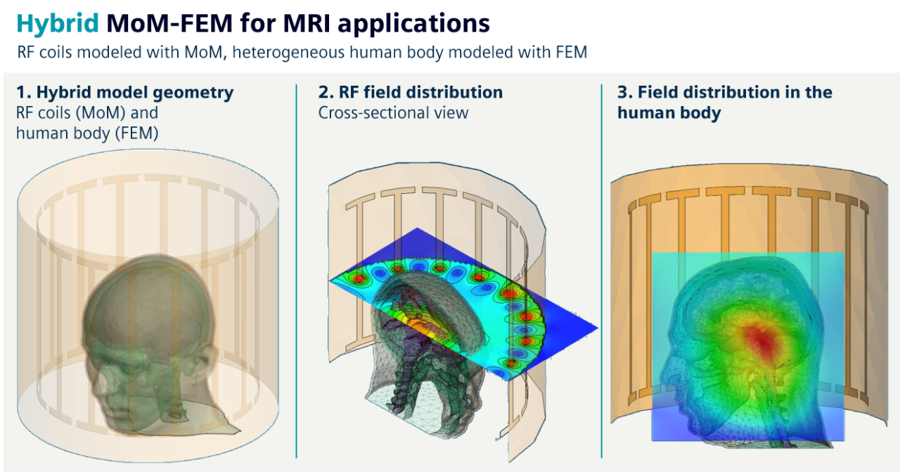
Hybrid MoM-FEM and MLFMM-FEM address a different class of problems, particularly dielectric structures in open space. FEM is used for complex volumetric regions, while MoM or MLFMM provides the coupling to the surrounding open domain. One important advantage is that the potentially large air region around and between objects does not need to be meshed as it would in a pure FEM approach.
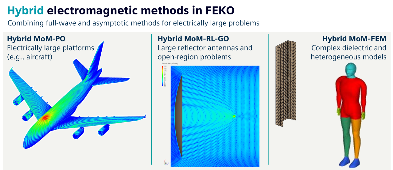
This combination is particularly useful in applications such as medical electromagnetic simulation. For example, the metallic coils of an MRI system can be modeled with MoM, while the heterogeneous human body is represented using FEM tetrahedral elements. MoM-FEM was introduced in 2005, followed by MLFMM-FEM in 2010.
Hybrid MoM-MTL was added with FEKO Suite 5.2 in 2006, extending the hybrid philosophy to cable and wire-harness applications. Multiconductor Transmission Line (MTL) theory efficiently predicts currents and impedance behavior in cables, while MoM accounts for electromagnetic radiation and irradiation. Their bidirectional coupling therefore provides an efficient approach for EMC problems in which cables interact with the surrounding three-dimensional electromagnetic environment.
The cable modeling capabilities support complex bundles and wire harnesses with multiple conductors, including coaxial cables, twisted pairs, shielded cables and ribbon cables, as well as the import of complex harnesses using the KBL format.

Expanding the simulation toolbox
FEKO Suite generations 5 and 6, released between 2005 and 2013, introduced several additional simulation technologies that further extended the range and scale of electromagnetic problems that could be addressed. A few notable developments are highlighted below.
Periodic Boundary Conditions (PBC) enable the simulation of a single unit cell of a repeating structure, significantly reducing memory and computational requirements. This makes them particularly useful for large or infinite periodic structures such as antenna arrays, metasurfaces and frequency-selective surfaces (FSS).
Adaptive Cross Approximation (ACA) reduces the memory and computational requirements of Method of Moments (MoM) simulations by compressing parts of the otherwise dense interaction matrix into a low-rank representation.
Large Element Physical Optics (LE-PO) allows electrically large mesh elements to be used instead of the approximately λ/10 discretization required by traditional Physical Optics (PO), reducing runtime and memory requirements for electrically large structures.
Higher order basis functions (HOBF) represent more complex current distributions on each mesh element, enabling accurate solutions with fewer and larger elements than conventional low-order basis functions such as RWG functions. Combined with curvilinear elements, they also provide a better geometrical representation of curved structures.

Bringing physics back to simulation: Characteristic Mode Analysis
FEKO introduced Characteristic Mode Analysis (CMA) in 2012 with FEKO Suite 6.2, making this advanced analysis method accessible to engineers for practical applications such as antenna design, antenna placement on platforms and the investigation of radiation mechanisms on complex structures.
Rather than focusing only on the response to a particular excitation, CMA provides insight into the fundamental resonant behavior of an antenna or the structure on which it is mounted. By examining the characteristic modes and their associated current distributions and radiation patterns, engineers can better understand how a structure naturally tends to radiate.
This physical insight can help determine suitable excitation locations, identify promising positions for antennas on a platform and understand how different modes contribute to the overall radiation pattern. Desired antenna behavior can then be achieved by appropriately exciting or combining these modes. This provides a deterministic, physics-based approach to antenna design. Rather than relying only on an optimization process to explore a large multidimensional design space, CMA gives engineers physical insight that can help guide the design from the outset.
The example shown here illustrates the design of an LTE antenna in a mobile handset based on the analysis of its modal current distributions.

From academic research to a mature EM simulation solution
By 2013, FEKO had established a strong technological foundation, with advances in MLFMM, solver hybridization, cable modeling, higher-order techniques and Characteristic Mode Analysis. These developments enabled engineers to tackle increasingly complex electromagnetic problems across a growing range of applications, from automotive antennas and EMC to mobile communications and medical applications.
This concludes Part 1 of the FEKO story, covering 1991 to 2013. In Part 2, we will follow its evolution from 2014 onward, exploring new technologies, expanding applications and the major milestones that shaped its journey into the Simcenter portfolio.