Accelerate antenna design optimization with Simcenter Feko and Simcenter HEEDS
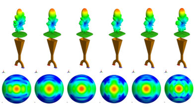
Designing high-performance antennas requires more than accurately predicting electromagnetic behavior. Engineers also need to explore design alternatives efficiently and understand the trade-offs between different performance objectives. By combining the electromagnetic simulation capabilities of Simcenter Feko with the automated design exploration capabilities of Simcenter HEEDS, engineers can move efficiently from simulation to optimized antenna designs.
From antenna simulation to design optimization
Antenna performance depends on numerous interdependent parameters, such as geometric dimensions, substrate properties, feed position and ground plane size. Simcenter Feko enables engineers to model these effects and evaluate antenna performance across different design variants using numerical electromagnetic simulation.
As the number of design variables and performance objectives increases, however, manually exploring these variants becomes increasingly challenging. Connecting Simcenter Feko with Simcenter HEEDS introduces automated optimization capabilities, including single- and multi-objective optimization, robustness analysis and reliability optimization, surrogate model creation, and workflow automation.
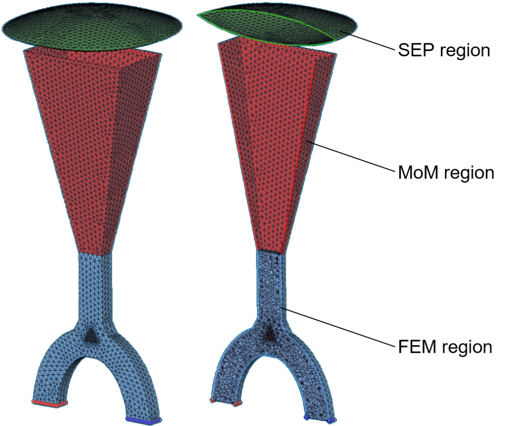
In this blog, we demonstrate this approach through the shape optimization of a dielectric lens placed on top of a horn antenna. The simulation uses a hybrid method of moments (MoM) and finite element method (FEM) solver in Simcenter Feko at 3.05 GHz. The FEM region represents the waveguide, including an anisotropic circulator, while MoM is used for the metallic horn. The dielectric lens is modeled using the surface equivalence principle (SEP). The objective is to optimize the lens shape to maximize antenna gain while making the gain pattern as rotationally symmetric as possible.
Parametrizing the antenna model for design optimization
To enable efficient design exploration, the lens geometry is parametrized using the NURBS tool in the CADFEKO module in Simcenter Feko. One octant of the lens is represented by a rational biquadratic Bézier surface defined by nine control points and nine weights. The complete lens is then constructed by cutting the surface along the z = 0 plane and mirroring it with respect to the symmetry planes x = 0, y = 0 and z = 0.
The control points of the Bézier surfaces have a geometrical meaning, making it straightforward to control G0– and G1-continuity along the patch connections. The resulting lens parametrization forms an 11-dimensional design space.
Four goal functions are defined to evaluate antenna performance throughout the optimization. Goal 1 represents the antenna gain in the boresight direction, while goals 2 and 3 describe the side lobe levels (SLL) in the E- and H-planes. Goal 4 represents the minimum gain along the θ = 15° isocurve. Maximizing goal 4 helps produce an almost rotationally symmetric gain pattern.
With the parametrized model and goal functions defined, the electromagnetic simulation is performed in Simcenter Feko to calculate the antenna responses and generate the relevant plots in the POSTFEKO module.
Connecting Simcenter Feko with Simcenter HEEDS
With the parametrized Feko model and simulation setup in place, the next step is to connect the workflow to Simcenter HEEDS. The Feko portal in HEEDS is configured by pointing it to the Simcenter Feko installation directories. The electromagnetic simulation workflow can then be defined in three main steps: opening the parametrized model in CADFEKO, running the Feko solver to compute the responses, and visualizing the results in POSTFEKO.
The resulting data is passed to Simcenter HEEDS, which determines the next set of design variables according to the selected analysis approach and automatically repeats the electromagnetic simulation workflow in Simcenter Feko. Both 3D and 2D visualizations from POSTFEKO are also available in HEEDS, allowing engineers to monitor the design and its corresponding performance throughout the optimization.
Exploring and optimizing antenna designs with SHERPA
Once the Simcenter Feko simulation workflow is connected to Simcenter HEEDS, the design space can be systematically explored and optimized. Simcenter HEEDS offers several approaches for design exploration and optimization, with SHERPA as its main optimization strategy. SHERPA stands for Simultaneous Hybrid Exploration that is Robust, Progressive, and Adaptive.
Rather than relying on a single optimization method, SHERPA simultaneously employs multiple search strategies and adaptively allocates computational effort to the methods performing best as the study progresses. This reduces the need for engineers to select a specific optimization algorithm in advance, making SHERPA particularly well suited for high-fidelity, simulation-driven design optimization where every evaluation counts.
In this example, a multi-objective optimization study is defined in Simcenter HEEDS to explore more than 150 antenna designs. Rather than producing a single optimal design, the study identifies a set of Pareto-optimal solutions representing different trade-offs between the defined performance goals.
Evaluating Pareto-optimal antenna designs
Once the SHERPA optimization is complete, the Pareto-optimal solutions can be analyzed using the postprocessing capabilities in Simcenter HEEDS. The Trade-offs tool under the Discover ribbon provides a visual representation of these solutions, helping engineers compare performance trade-offs and select an appropriate antenna design.
In this example, design 148 provides a good balance between the optimization goals, improving antenna gain by 22% and the roundness KPI by 59%.
Conclusion
Combining Simcenter Feko with Simcenter HEEDS enables engineers to systematically explore a broader antenna design space while maintaining high-fidelity electromagnetic simulation at the core of the process. Automating the repeated simulation and evaluation of design variants can help reduce design time and identify promising solutions while supporting informed trade-offs between competing performance goals.
While this example focuses on antenna design, the same approach can be extended to other electromagnetic applications, including the optimization of EMC behavior and radar cross section (RCS).