Saving Your Permanent Magnets From Demagnetization
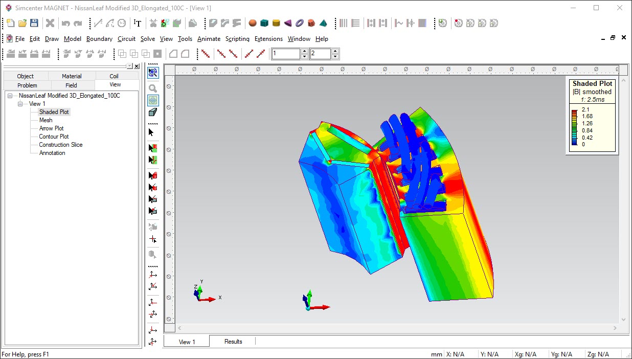
Safeguarding the performance of electric devices containing permanent magnets (motors, generators, actuators, etc.) against demagnetization is an integral aspect of ensuring robustness of electric machines. Identifying the regions of permanent magnets that may be susceptible to demagnetization is a difficult modeling task. This is especially true in 3D, not least because it may result from both electrical and/or environmental anomalies. Simcenter MAGNET 2020.1 includes a new 3D demagnetization modeling capability. With this feature, you can take protective measures during any phase of the design process; well before physical prototyping.
What is Demagnetization?
Permanent magnet demagnetization is the change in the remanence (the magnet’s strength) and the coercivity (the field needed to demagnetize it completely) of magnets (see Figure 1). The changes can happen from elevated temperature or if a high enough magnetic field opposes the magnet’ intrinsic fields (due to electrical faults). During a machine’s operation demagnetization may take place dynamically and must be tracked continuously.
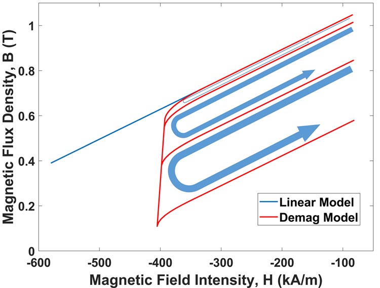
Figure 1: Characteristics changes in permanent magnets from demagnetization
Hence, machine designers must carry out coupled electromagnetic-thermal simulations and/or simulations of electric faults (short circuits, etc.) to assess the feasibility of demagnetization and take preventative steps early in the design process. For 3D devices demagnetization calculations can be especially difficult. This is because demagnetizing effects of esoteric end-turn geometries such as a hairpin or involute configuration are difficult to compute.
Using Simcenter MAGNET 2020.1, we examine the 3D demagnetization proximity field calculations. The demagnetization proximity field quantifies how close any point of a magnet is susceptible to losing its intrinsic field strength.
Two examples will help illustrate. The first is related to the aerospace industry, and the second for the automotive industry.
Aerospace: Axial Flux Electric Motor
An axial flux motor developed as an e-taxiing motor for the Airbus 321 aircraft is shown in Figure 2. It is a 10 pole 12 slot machine that is inherently a 3D electromagnetic device.
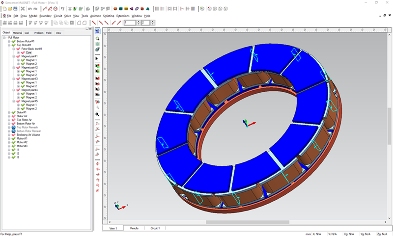
Figure 2: A 10 pole 12 slot axial flux machine designed for e-taxi of A321 aircraft
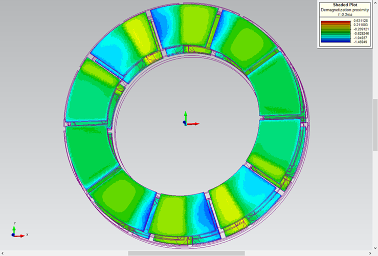
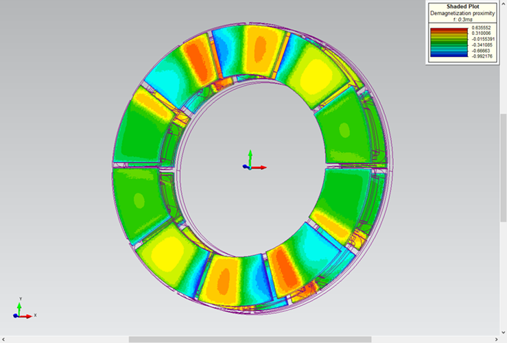
For this machine, here are the demagnetization proximity field at 20 degrees (left) and at 100 degrees Celsius (right).
Figure 3: Demagnetization proximity field at 20 Degrees (left) and at 100 Degrees (left)
There is a marked difference between the results. When the temperature reaches 100 degrees, parts of the magnet (seen in bright yellow) will weaken. In Figure 4, we see the impact on the cogging torque. The ability to differentiate the effects of temperature changes on the cogging torque due to demagnetization is a testament of MAGNET’s modeling capability to capture even the finest changes to a machine’s performance from this phenomenon.
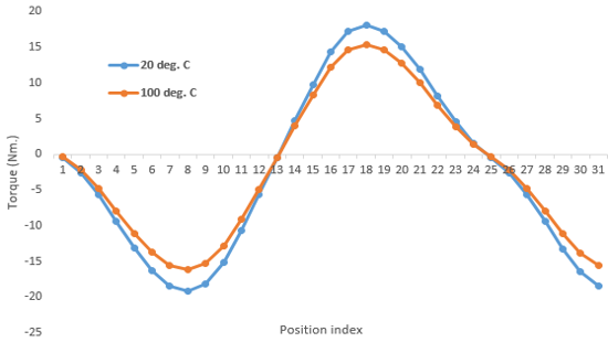
Figure 4: The effects of demagnetization on the cogging torque of the 10-12 axial flux machine
Automotive: The Prius Motor
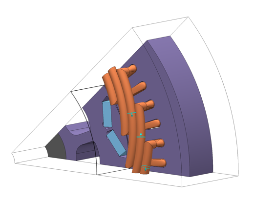
Next, let’s consider the effects of demagnetization on the Prius motor. Notice the prominent 3D winding end-turn geometry of the model.
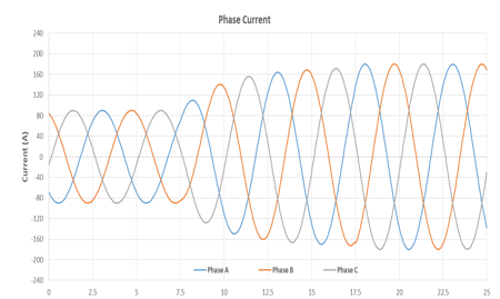
First, the effects of demagnetization on the torque or power output from current surges will be considered. Then, the effects of system faults that results in an irreversible demagnetizing effect on the magnets will be examined. For the first scenario consider the case of a current surge (an abrupt increase in the current waveform) of the motor.
Figure 5: The partial model of a Prius motor (left) and a current surge (right)
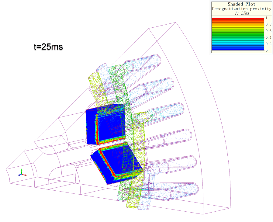
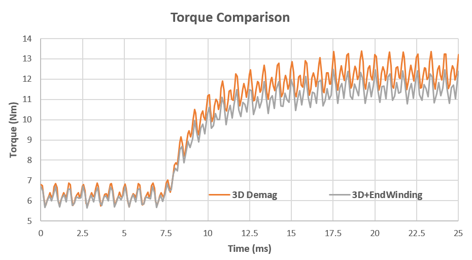
The current surge may damage the magnet segments. Its effect has been calculated by carrying out a 3D transient simulation. Figure 7 shows the demagnetization proximity field and the torque output of the model. In this case, Simcenter MAGNET has dynamically tracked the demagnetization proximity field for the case when the end turn effects are included or neglected. The results clearly show that when end turns are included the machine output, which is directly related to the demagnetization pattern, is different.
Figure 6: The magnet segments demagnetized (left) and the effects on torque output (right)
Another potential impact of demagnetization is the irreversibility of the loss of remanence. Often, after a fault, the power system may recover and the current/voltage load returns to their rated values. It would be ideal if the effects of demagnetization were reversible and the magnets retain their original remanence after such an event. Unfortunately this is not the case; the magnets require remagnetizing which is an expensive proposition. A machine designer must be able to simulate and predict the effects of such events and take measures to safeguard against eventualities requiring expensive maintenance. The following example illustrates this.
Irreversible Demagnetization
On Figure 7, the effects of irreversible demagnetization has been calculated on the back EMF of the Prius motor. It shows a voltage short circuit event followed by the system’s recovery. After recovery, the phase voltage amplitude is slightly lower than prior to the fault. Though in this instance the effects are not catastrophic the example shows the irreversible effects of demagnetization on the machine. The animation below shows the transient simulation of the magnets undergoing partial but irreversible demagnetization.
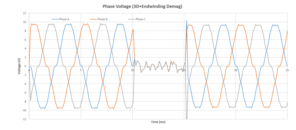
Figure 7: The back EMF profile of the Prius machine before and after a short circuit event
Transient simulation of the magnets undergoing partial but irreversible demagnetization.nt
Summary
For modern machine designers the ability to predict the effects of demagnetization and take preventative measures are critical aspects of ensuring robust machine performance. Simcenter MAGNET 2020.1 can fully model these effects in 3D. They will help the next generation of machine designers achieve their design goals giving ample confidence that the machine’s magnets will be protected under adverse conditions.
