Mastering bevel gears simulation towards quiet transmissions
The rapid growth of electrification is shaking the foundations of vehicle powertrain development, as the automotive industry can no longer leverage their 100 years plus experience in ICE (internal combustion engine) powertrain development. On top of that, the market environment is changing quickly, due to the altering regulations and many newcomers entering the market. The question is: “How to stay ahead of the competition and differentiate for electric drives?”.
Noise and vibration play an essential role in the overall comfort of a vehicle. The advent of electric vehicles (EV) makes the contribution of the gearbox to the entire noise signature more prominent [1]. Next to planar gears (that transfer rotational energy in the same plane), also bevel gears are used to transfer rotational energy into another rotational direction (e.g. in the vehicle differential). Bevel gears are instrumental for the mechanical design and operation of the vehicle, but they represent a challenge for design engineers as their noise and vibration performance is more difficult to predict and optimize.
For mastering bevel gears simulation towards quiet transmissions, Siemens Digital Industries Software has developed an innovative numerical analysis solution for bevel gear transmission acoustic emission. This involves using a 3D gear contact force model within the Simcenter 3D multibody system dynamics simulation environment, enabling vehicle manufacturers to design and deliver tomorrow’s quiet transmissions within the growing EV fleet.
The bevel gear vibration challenge
Gear meshing refers to the way in which the gear teeth are inserted between the teeth of the mating gears, while the gear pair is rotating. Like spur and helical gears (planar gears), the loading of the bevel gears results in a strongly nonlinear gear meshing process, which is known to generate unwanted vibrations. Unlike spur and helical gears, the accurate modeling of this bevel gear tooth meshing process is made more complex due to the three-dimensional motion transfer between the bevel gears elements. For a proper design of your bevel gears, the following aspects need to be considered:
- Gear pairs are designed with a certain microgeometry, leading to a certain transmission error (TE). Typically, this results in:
- a high peak-to-peak TE in unloaded conditions, but
- a lower peak-to-peak TE at the design load.
- In contrast to cylindrical gears, there exists no concept of a perfect involute tooth profile. The actual tooth flank and microgeometry topography is completely determined by the gear manufacturing process.
- System compliance will cause gear pair misalignment under load, influencing the dynamic TE and contact pattern
To address your bevel gear vibration challenge, we recommend that you:
- analyze how the vibrations (arising from TE) are transmitted via the bearings to the housing;
- adopt a system-level approach to design, simulate and analyze the gearbox/drivetrain.
The design optimization of bevel gear boxes in terms of NVH requires more knowledge on the effects of sensitivity to these errors. This is a crucial aspect to bevel gears design for industrial product manufacturers. It is mandatory to optimize and validate the bevel gear design before production to avoid excessive end-of-line testing, thus reducing expensive prototyping to a minimum.
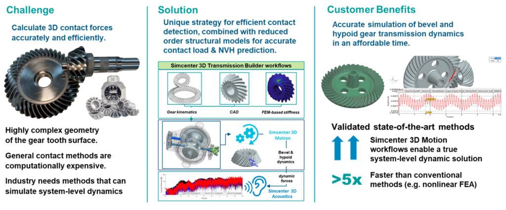
A novel solution for bevel gear modeling and simulation
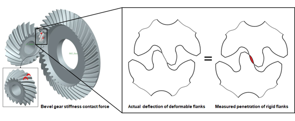
Simcenter 3D Motion’s new bevel gear contact element [2] provides a modular approach to bevel gear simulation, that bridges the gap between accurate tooth flank description, fast 3D contact detection and contact force calculation with various level of accuracy, into system-level calculation of dynamics and acoustics. The bevel gear contact element includes three types of contact forces: a stiffness gear contact force (analytical of FE-analytical), a viscous damping gear contact force, and a Coulomb-based friction force. The approach to contact force calculation and a resulting contact force distribution are shown in Figure 1, see also [4].
The new contact method has been implemented as a novel contact element in Simcenter 3D, where it equips the multibody solver [3] with the capability to analyze both straight and spiral bevel gears, and subsequently optimize them. The capabilities include:
- accurate & efficient contact models that can be used in dynamic time-domain simulations;
- 3D contact detection to determine how microgeometry and gear pair misalignment affect TE;
- embedded in a multibody simulation framework to enable system-level gearbox simulation.
This blog post focuses on using the bevel gear contact element for system-level application to noise and vibration challenges, which is elaborated in the paper of Dr. Mathijs Vivet et al. [4] at the upcoming VDI International Conference on Gears 2023. Acoustics simulation can be done to evaluate bevel gears as a source of excitation, and as a transfer path for noise and vibration. Smooth processes are available in Simcenter 3D to export the bearing reaction loads, or alternatively the housing vibrations directly [4], from the dynamic simulation and apply them as excitations for vibro-acoustic simulations. The new bevel gear element enables accurate prediction of noise and vibration performance in an efficient way [4], thus serving the industrial end user needs for the quiet transmissions of tomorrow.
Bevel gearbox analysis using dynamic and acoustic simulations
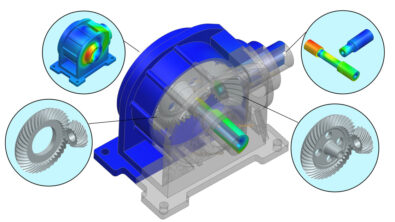
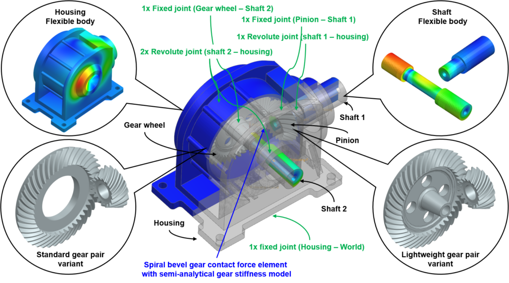
When the vibrational gear contact forces, arising from the gear tooth meshing, are transferred via shafts and bearings to the gearbox housing, the latter vibrates and causes sound emission to its environment. To correctly predict the acoustic emission of a bevel gearbox in Simcenter 3D, the multibody simulation [5] is first performed using flexible multibody system dynamic simulation to compute the housing vibrations due to the dynamic gear loads. Afterwards, the acoustic simulation [6] couples these housing vibrations with the acoustic model of the exterior air to solve and reach the vibroacoustic design objectives with Simcenter 3D. Figure 2 presents the flexible multibody model of the spiral bevel gearbox that is studied in [4]. The model makes use of the new FE-Analytical gear contact method to analyze the behavior of two spiral bevel gear pair variants, where one variant has a standard blank design and the other has a lightweight blank design.
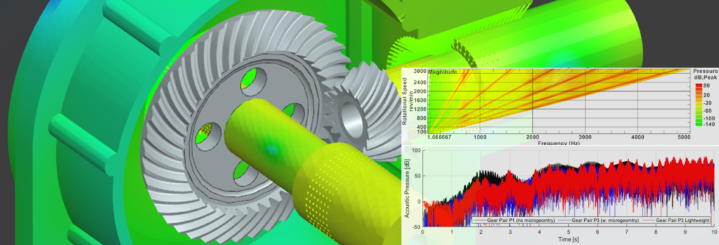
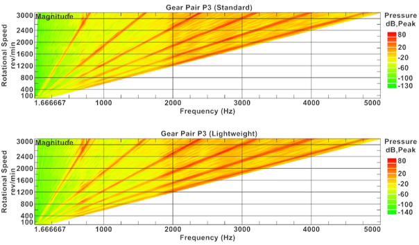
The acoustic emission of the spiral bevel gearbox is computed from a dynamic run-up simulation during which the pinion shaft is accelerated from 0 to 3000 RPM over the course of a 10 seconds time interval, while a constant pinion-load of 100 Nm is applied. Before continuing with the acoustic simulation, an order analysis is first performed to identify the critical gear meshing orders, and to determine the order resolution with which to compute the gearbox acoustic emission later on. The gear meshing frequency is determined by the number of tooth impacts that occur during a single revolution of a chosen gear reference shaft. As we have seen that these impacts are strongly tied to arising vibrations and thus also to the emitted gearbox noise, it follows that the gear meshing orders can be found back easily in a Campbell diagram of the microphone acoustic pressure. The Campbell diagrams for the standard and lightweight gear pair variants are presented in Figure 3. Comparing both diagrams, the gear meshing orders are clearly visible as harmonics of 16, given that the spiral bevel pinion under analysis has 16 teeth. It should also be noted that the lightweight gear pair variant shows additional side bands, which are traced back to the presence the lightweight features (i.e. holes). A detailed analysis is found in [4].
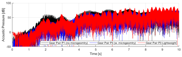
Having performed the vibroacoustic simulations, the resulting sound can be generated thanks to Simcenter 3D’s new auralization capabilities. These not only enable hearing the noise, but also provide sound quality metrics to better understand its perception by the human ear. Figure 4 presents the auralized microphone sounds for the gear pair variants that are analyzed in [4]. The standard gear pair variant was simulated once without microgeometry (P1 variant), and once with microgeometry (P3 variant). The gearbox noise, produced by the lightweight gear pair variant (P3 Lightweight), which is based on the standard P3 variant, is also analyzed. Comparison of the sound levels reveals that the standard gear pair variant with microgeometry (which results in a smoother tooth engagement under load) is less loud that its counterpart without microgeometry, see [4] for more information. However, one can hear that the lightweight gear pair variant is louder that its standard counterpart, and that the presence of the holes is audible in the generated sound level. These differences can also be identified by the human ear when listening to the sound files, presented in Figure 5.
Note: In the videos of Figure 5 the auralized sound of the gearbox during a runup from 0 – 3000RM over a period 10s was edited over a motion animation of the same gearbox yet over a shorter duration, since at high rotational speeds it becomes difficult to display meaning visual results of the gear pair’s rotation in the gearbox. The motion animation is there to help the reader in more easily linking the produced sound to the gearbox model variant
Conclusions
Numerical analysis of a spiral bevel gearbox’s dynamics and acoustic emission is presented. A novel 3D hybrid (FE-analytical) gear contact model is used to accurately compute the gear contact forces within a multibody system dynamics simulation environment, from which the effect of bearing reaction loads can smoothly be taken from the dynamic simulation and applied them as excitations for vibro-acoustic simulation. These new capabilities of Simcenter 3D will be available in June 2024, enabling vehicle manufacturers (and other manufacturers that use bevel gears as crucial components in their mechanical design) to predict bevel gears noise and vibration behavior in the design phase, which is crucial to achieve quiet transmissions.
On Friday September 15, 2023 at the VDI International Conference on Gears 2023 in Garching near Munich (Germany), Dr. Mathijs Vivet presented the paper [4], detailing on the bevel gear contact element and its system-level application to address noise and vibration challenges. For more information, refer to the Conference website.
Acknowledgements
The R&D work leading to this publication has been performed in the frame of the VLAIO Innovation Mandate Project “Advanced techniques for system-level simulation of Hypoid and bevel gEAr Dynamics” (“AHEAD”), conducted by Dr. Mathijs Vivet, with industrial partner Siemens Digital Industries Software and academic research partner KU Leuven, project nr. HBC.2019.2177, from 01/09/2019 – 31/08-2022.
References
- [1] Jonas Verhoogen and Jonathan Melvin, “Bevel gears whine no longer due to unseen pressure”, Simcenter Blogpost, January 5, 2022.
- [2] Mathijs Vivet, “Simulate Bevel Gears Accurately and Efficiently”, Simcenter Blogpost, October 28, 2022.
- [3] Mathijs Vivet, Alessandro Libralato, Jonas Verhoogen, Pavel Jiránek and Tommaso Tamarozzi, “Advanced modelling of straight bevel gear contact for multibody simulations”, Proceedings of ISMA Conference 2022, Leuven, Belgium, September 12-14, 2022.
- [4] Mathijs Vivet, Ali Rezayat, Jonas Verhoogen, Korcan Kucukcoskun, Stijn Donders, “Numerical analysis of bevel gear transmission acoustic emission using a 3D gear contact force model within a multibody system dynamics simulation environment”, Proceedings of VDI International Conference on Gears 2023, Garching, Germany, September 13-15, 2023.
- [5] Siemens Digital Industries Software, “Simcenter 3D Motion Simulation”, Retrieved 2023.
- [6] Siemens Digital Industries Software, “Simcenter 3D Acoustic Simulation”, Retrieved 223.