Bevel gears whine no longer due to unseen pressure.
Introduction
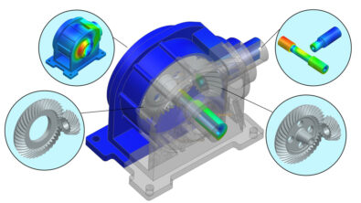
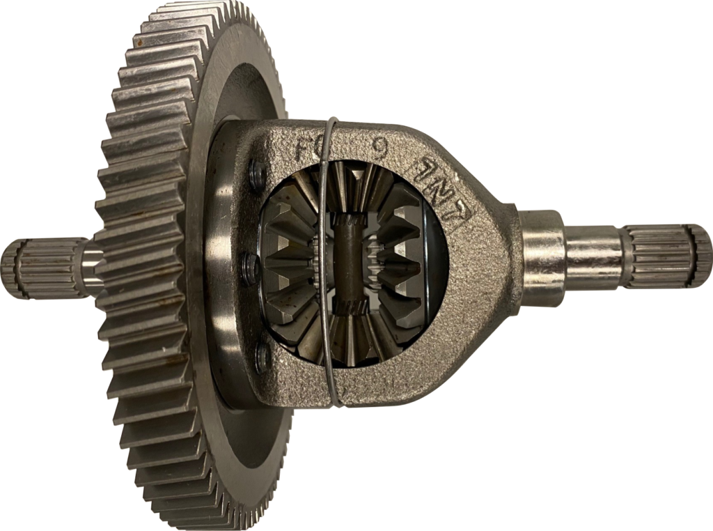
Drivers are familiar with using gears to overcome the limitations of their internal combustion engine (ICE). In addition to the gearbox, vehicles have many other gears for a range of purposes, such as the differential. Where to change the axis of rotation from that of the engine to that of the wheel, we use bevel gears. Furthermore, the differential’s gears carry heavy loads, to dissipate the loads we use spiral gears, further increasing the gear’s complexity.
Electric motors have very different limitations to that of an ICE. In this blog, we consider these differences and the new engineering challenges faced by gear designers.
The raw power of electric vehicles.
The Tesla Model 3 can do 0-60 in 3.1 seconds without changing gear. It can do this because electric motors can produce 20,000 rpm, far more than an ICE. Furthermore, electric motors can provide efficient power delivery across a wide range of speeds starting from zero mph. With the ability to reach high speeds and torque without gears, one may think there is no need for a gearbox in an EV.
What about the differential and its bevel gears?
Compared to an ICE, an electric motor is relatively small and light. Therefore, you may think that there is a motor for each wheel. If such a design had all the wheels managed by one controller, you would remove the need for a differential. You may then conclude that there is no need for any gears in an EV.
Gears everywhere.
A four-motor design is not entirely wrong. Some cars have four motors, one to each wheel, the 4-Motor Acura EV Concept being an example. However, these can still have reduction gears to trade torque for road wheel speed and provide the desired vehicle characteristics. Although 4-motor EVs exist, the most popular EV, the Tesla Model 3, has only two motors and subsequently requires differential gears. So EVs, such as the Tesla Model 3, have gears in the differential and reduction gears in a transmission.
Go even faster with even more gears.
What about the flaps on the steering wheel of the all-electric Formula-E car? Two of those flaps are to change gear, and it is not just Formula-E cars. Other EVs such as the Porsche Taycan also have a multi-speed gearbox. In both cases, these are high-performance cars where high acceleration is advantageous at both low and high speeds. The low-speed gear helps the car get off the start line and out of the low-speed corners. At the same time, the high-speed gear allows the vehicle to continue to accelerate and perform high-speed maneuvers. Removing the gearbox would compromise either the low or high-speed performance of the car.
In racing, a fraction of a second can be the difference between the front and back of the grid. With the demand for performance being so high an extra gear can be essential. However, in most road vehicle cases, the additional weight of the gearbox and subsequent reduction in range would offset any speed advantages and therefore gears are generally not present.
Can we simulate all gear types?
In a previous blog, we discussed gear whine and its importance in EVs because it becomes the dominant sound when there is no ICE noise. We explained how gear meshing and gear deformation are important for the Noise, Vibration, and Harshness (NVH) performance of the entire vehicle. The blog then continues to explain how Simcenter 3D can consider such designs and optimize them. Until now, it was possible to consider the gears in a multi-speed gearbox and the reduction gears in Simcenter 3D, but this was not the case for spiral bevel gears, such as those found in the formula-e BMW season 5 powertrain.
Bevel gears
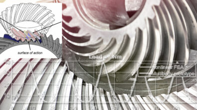
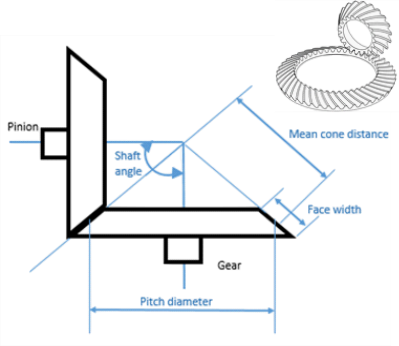
When the motor’s orientation and the wheels’ axis are not aligned, there is a need to transfer the axis of rotation with bevel gears. To create a bevel gear, the face of the gears are pitched in the same way as a carpenter forms a miter joint, as shown in Figure 2. To reduce the size of the required gears but maintain their load capacity the teeth of a bevel gear are often aligned in a spiral. As can be seen in the image insert of Figure 2, the teeth of a spiral bevel gear are not straight. This spiraled characteristic of the teeth allows for more tooth overlap giving greater load capacity. It also has the added benefit in that it improves the gradual engagement and disengagement of the tooth contact, improving the overall NVH of the vehicle.
Spiral bevel gears
Unlike cylindrical gears, the geometry of spiral bevel gears cannot be described by a set of gear macro and micro geometry parameters. The gear geometry of spiral bevel gears is much more complex and can only be described by its manufacturing process. Until now, there have been no good system simulation tools that can describe the actual spiral bevel gear geometry and consider its influence on system-level NVH performance. With the release of Simcenter 3D 2022.1, a new dedicated gear contact element will be able to consider the exact tooth flank geometry resulting from bevel gear manufacturing. Moreover, this gear contact method allows the engineer to consider the influence of dynamic conditions such as loading and misalignment on contact detection.
Visualize the force
As you can see in the video below, the engineer can simulate the meshing of the gears and see the contact force vectors. Additionally, they can see that as the load increases, the force vectors become higher, more spread, and have an increased contact ratio.
Gears must have a uniform load distribution over the tooth flank during operating conditions. Contact pressure and bending stress increase locally if the load is not uniformly distributed. This raises the risk of tooth surface damage and breakage, respectively. When only looking at system-level results such as transmission error, bearing forces, etc., it is challenging to debug and explain critical events such as excessive loading from misalignments and wedging. The new tool helps engineers know that the gears are misaligned and the misalignment effects in a simple visualization. The video below shows a significant misalignment, with a wedging situation that exerts forces on both sides of the tooth.
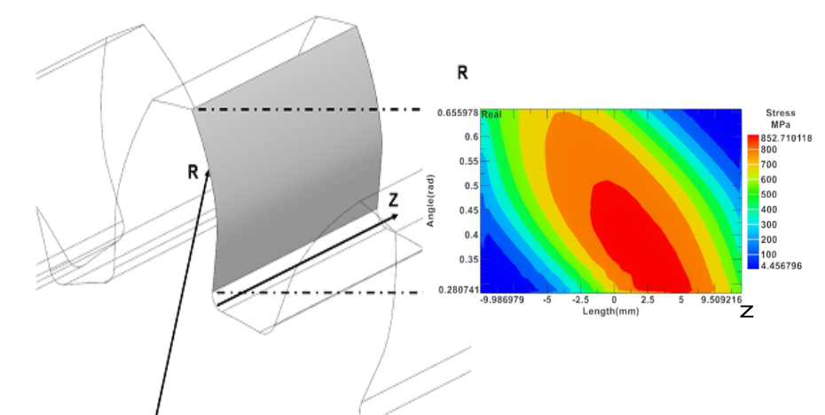
Until now, there were no dedicated gear post-processing capabilities in Simcenter 3D. In this release, users can visualize the contact force vectors and maximum context stress distribution on a tooth flank. A contact pattern is a figure that shows gear contact stresses with respect to the local R-Z coordinate plane of the gear tooth, as shown in Figure 3. Contact stress distributions plots represent a given mesh cycle and operating condition. A contact pattern plot gives the user direct insights into the influence of microgeometry and misalignment.
Conclusion
Despite the lack of a traditional multi-speed gearbox, there is still a requirement for numerous gears in an EV. Therefore, to ensure the NVH rating of an EV, good meshing of all gears is essential. With Simcenter 3D 2022.1 an engineer can complete all of the gear and system NVH analysis in one environment.
Updates in this Simcenter edition include improvement to the visualization of forces, contact, and pressure distribution of gear faces. Additionally, It is now possible to describe the complexity of spiral bevel gears by their manufacturing process.
Acknowledgments
“Siemens gratefully acknowledge the VLAIO (Flemish Agency for Innovation & Entrepreneurship)
through its Innovation Mandate Project AHEAD (nr. HBC.2019.2177), which has made this research possible.”
More in Simcenter 3D 2022.1
Simcenter 3D is the most comprehensive and fully integrated CAE solution. When the gear specialist completes their analysis, the results are instantly available to other engineers working on the same vehicle. This capability sees dramatic enhancements in this release with Teamcenter share. Teamcenter share is a collaborator service that works across NX, Simcenter 3D, STAR-CCM, and many other tools. This release has many more highlights, find out more in our YouTube Premiere.