How features in Simcenter Amesim 2404 accelerate all aspects of Formula Student developments
Introduction
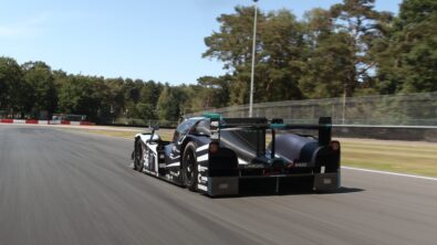
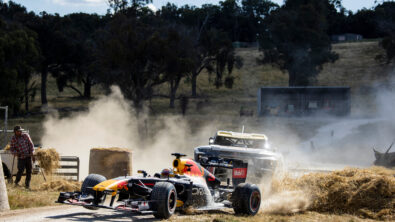
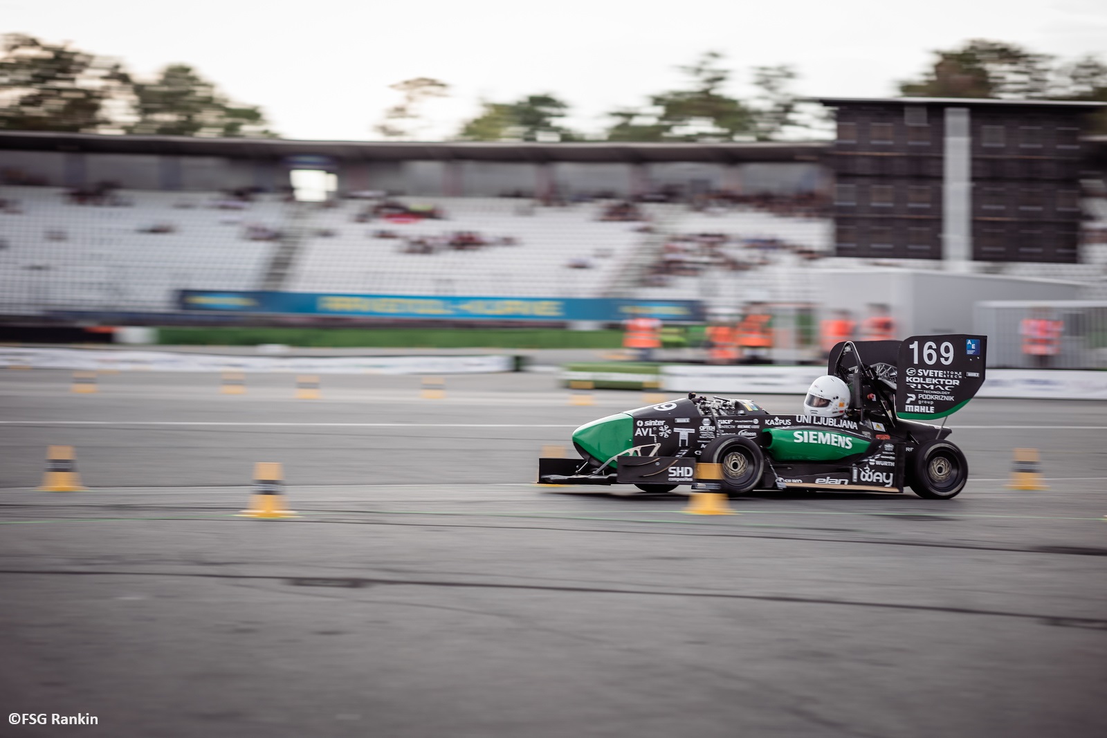
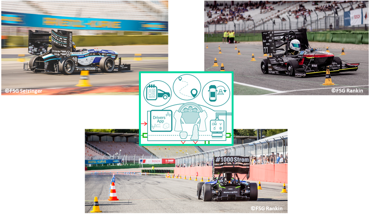
All traditional car manufacturers are currently focused on making the switch to electric vehicles, and the same is happening in the world’s biggest engineering competition — the Formula Student. In this ever-growing international design competition, teams of university students build a single-seated formula-style race car in less than one year and race it against other teams’ cars. There are hundreds of teams worldwide, competing every year at events all over the globe. Formula Student fast-tracks the automotive design process to give students hands-on experience in not only the engineering tasks themselves but also the critical task of project management. Goals need to be set, different departments of the team coordinated, and progress monitored.
Formula Student is no newcomer to electric cars. At Europe’s biggest Formula Student event, the Formula Student Germany, they have been competing since 2010. This year will be the first year in which only electric vehicles are allowed to enter the competition in Germany. This means that a lot of teams are adopting an electric powertrain for the first time. But even teams experienced in electric racing must find new ways to innovate and make their cars faster. System simulation is a powerful tool to augment and facilitate this design process.
Formula Student race car development
The student teams have less than one year to go from drawing board to racetrack. This leads to an extremely short development cycle and limited time on the test track. Furthermore, the financial and human resources of the teams are highly constrained and need to be managed wisely.
Typically, the design process of a Formula Student racecar follows these stages:
- Overall goals for the car are set, commonly by utilizing a simplified lap time simulation (LTS). The LTS uses a simplified vehicle model (e. g. point mass or bicycle model) which assumes steady-state conditions to determine relative performance sensitivities of general vehicle parameters like weight, power, grip, etc. Using these sensitivities, trade-offs can be evaluated, and a general car concept determined. This means choosing the chassis type (steel tube frame or carbon fiber monocoque), the powertrain architecture (how many motors, location of the motors), the tire type and size, etc.
- From the overall concept and goals, requirements for the individual subsystems and parts of the car must be determined. This ensures that every team member is working in the right direction, enabling monitoring of goals, and ensuring that resources are allocated to where they will have the greatest impact.
- Using these requirements, the design of the individual parts can proceed.
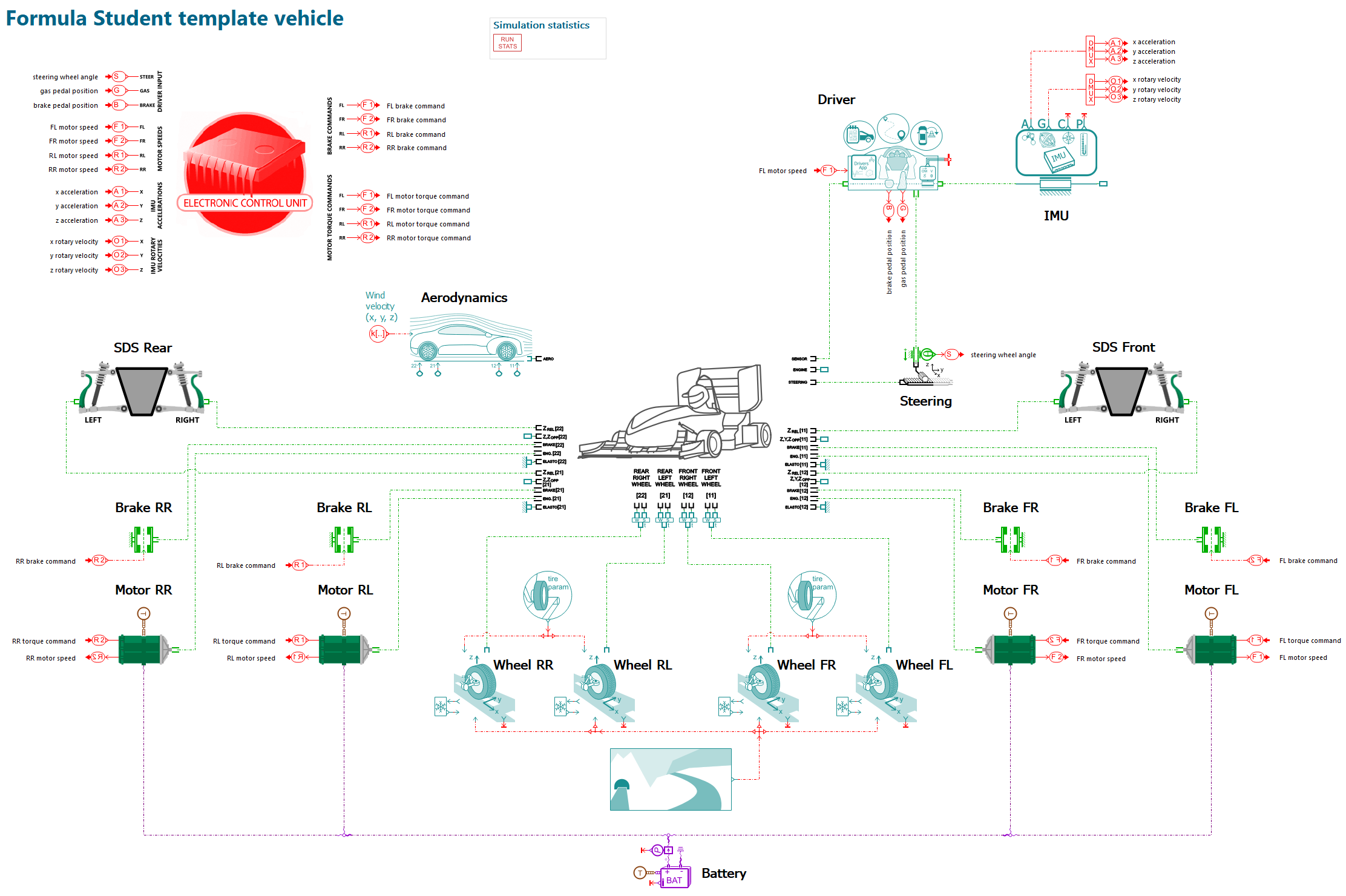
Out of these stages, the second one is often the most difficult to navigate, due to the highly complex interaction of subsystems in the car. It is difficult to predict the impact of changes being made to these subsystems. Especially for a team dealing with a fully electric system for the first time, the complexity can be daunting. Here is a diagram of the components of an electric powertrain and how the design parameters are interconnected:
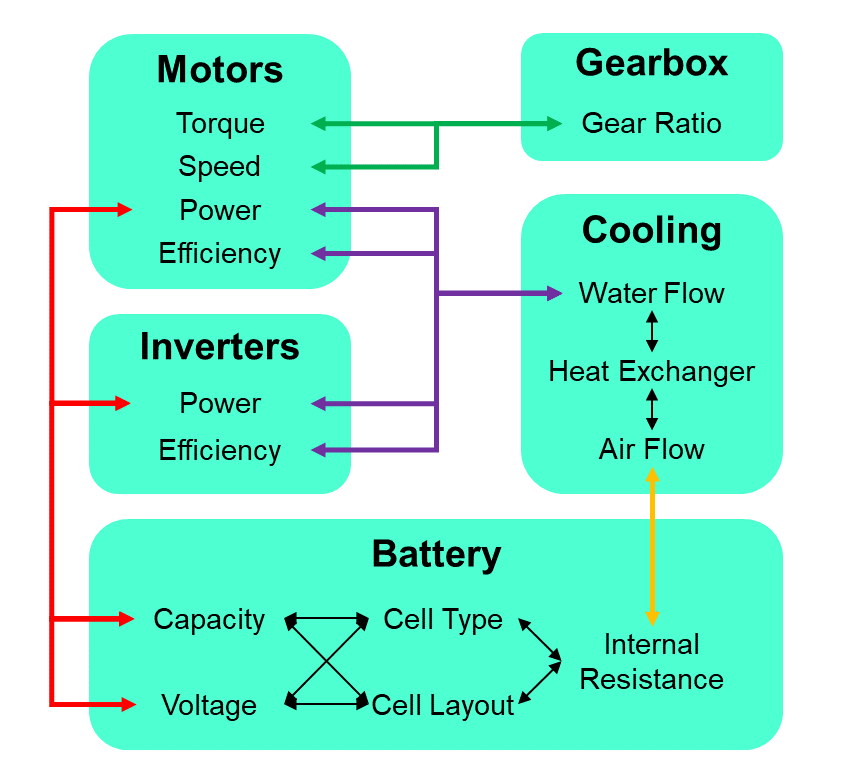
Crucially, it is the second step that decides the direction of development and resource allocation. These decisions need to be made early and confidently, especially if they are related to big changes in the car. If something goes wrong here, some parts of the car will be overengineered, meeting requirements many times over — other parts may not fulfill them at all, leading to failure on competition day. How do we ensure that the individual subsystems have requirements that will fulfill the overall goals without unnecessarily exceeding them? And how do we make sure that new components will work well in the car, considering the complex interactions between all the subsystems?
The answer is system simulation with Simcenter Amesim. Using Simcenter Amesim, the transient physical behavior of a Formula Student race car can be predicted throughout a single lap, a whole race, or any given specific driving scenario, enabling analysis of subsystem performance in any situation. Utilizing the full depth of Simcenter Amesim’s multi-physics libraries, subsystems can be modeled in any level of detail, from simple, functional models to highly detailed, physical ones. This allows the model to be adapted continuously throughout the design process to fit the needs of the current stage in the development cycle. When individual components of the vehicle are being designed, the model can be updated with the latest component specifications to monitor progress and verify that all goals are still being met. Controls can be developed, verified, and calibrated alongside this process.

Modeling process
Formula Student chassis model
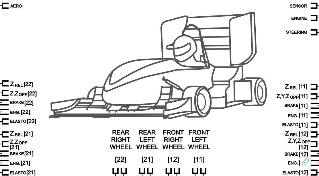
To model the chassis, the 15 degree-of-freedom (15 DOF) chassis component from the Simcenter Amesim Vehicle Dynamics library is utilized. This is a multibody system consisting of the carbody, spindles, wheels, and steering rack. All vehicle subsystems are connected to this component.
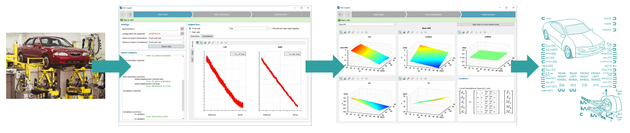
The kinematics of the vehicle are modeled linearly and defined using general kinematic parameters (caster angle, kingpin angle, roll center height, etc.). This allows an easy workflow and streamlines the process of performing batch runs, where one or more system parameters are varied across multiple simulations to determine their effect on vehicle behavior. The linear kinematic definition is thus especially useful early in the development cycle.
At a later point, when detailed vehicle dynamics analysis should be performed, the kinematic definition can be switched to the non-linear mode. This can be done in the same model, without changing any other subsystem, thus allowing for a seamless transition. The non-linear kinematics are defined using lookup tables, which can be created in Simcenter Amesim from test bench data, general kinematic parameters, or suspension hardpoint locations.
Formula Student driver model
The new driver component in Simcenter Amesim 2404 enables the simulation of any of the Formula Student disciplines. To simulate the “Autocross” (a qualifying-style one-lap race against the clock) or the “Endurance” (a 20- to 30-minute endurance race on the same track as the “Autocross”) a longitudinal and lateral controller with MPC (Model Predictive Control) logic can follow a given track and velocity profile.
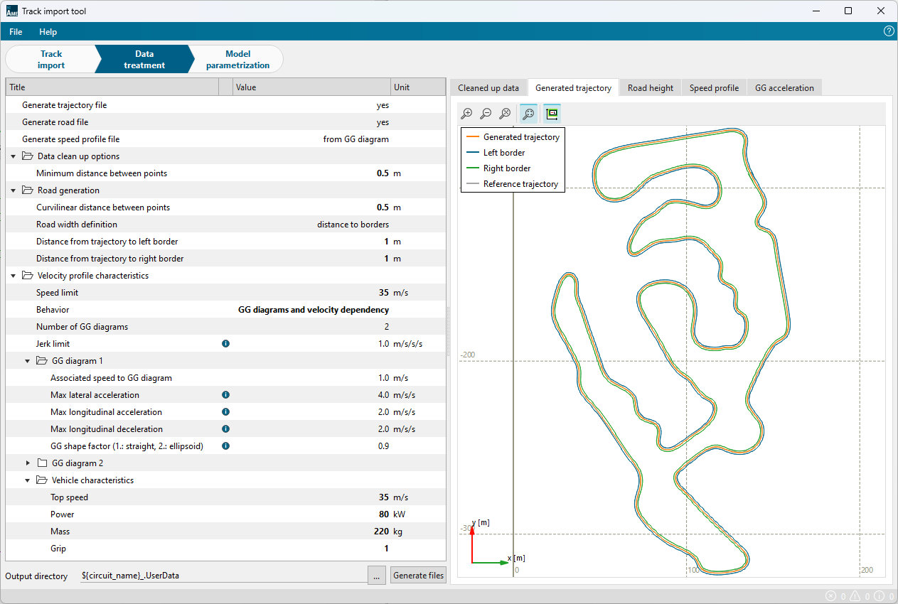
The track can be imported using the Track Import Tool, by supplying either a gpx or an XY data file, or utilizing the route planning function to import any major racetrack in the world. The velocity profile can be generated in Simcenter Amesim as well by supplying the G-G-V-diagram of the vehicle.
From this diagram, which specifies the maximum longitudinal and lateral accelerations at various velocities, Simcenter Amesim will then calculate the optimal velocity profile. For our test case, we imported the track of the Formula Student Germany at Hockenheim and generated a corresponding velocity profile for our vehicle.
The other driver option is the Maneuver Analyzer, which allows the simulation of one of numerous predefined maneuvers. This enables the simulation of the “Acceleration” Discipline (75 m drag race from a standing start), the “Skidpad” Discipline (steady-state cornering in a figure-of-eight circuit), or of other specific driving situations throughout a racing lap. The predefined maneuvers include braking in a turn, double lane change, fish hook and many more. The vehicle behavior can then be analyzed in detail in these specific scenarios, for instance by running a batch study of one kinematic parameter in one of the maneuvers.
In summary, Simcenter Amesim makes the simulation of any Formula Student discipline and any other driving scenario possible. The switch between the two driver options can be made seamlessly in the same model.
Formula Student vehicle subsystems
Corresponding to the concept stage of the development cycle, the subsystems of the vehicle are modeled with a simplified, functional approach. As the team progresses along the development cycle, the subsystem models can be expanded one by one to enable a more detailed analysis. The extensive multi-physics libraries in Simcenter Amesim can be used to model the systems in any level of detail, and for most of the subsystems, there are already more detailed models ready to be selected. Here is a short summary of the subsystems and their models:
- Suspension, consisting of an independent spring-damper-system for each wheel and optionally an anti-roll bar.
- Tires, are represented by a simplified Dugoff model (linear tire stiffness up to grip limit) but can be switched to a more detailed Pacejka 97 model.
- Steering system, including steering column, rack, and pinion.
- Brakes, including rotary friction components (several different friction models can be incorporated).
- Wheel hub motors (functional electric motor model and simple gear ratio).
- Battery, represented as an advanced equivalent circuit model. Numerous tools are available for parametrization. Many detailed effects (faradaic efficiency, hysteresis, diffusion, …) can be captured.
- Aerodynamics, can be a simple model with drag and lift coefficients but also switched to a more detailed model with the option to supply a full aero map.
- Controls, including a battery power limiter required by the Formula Student regulations.
- IMU (inertial measurement unit) to sense accelerations and rotary velocities which can be used as inputs for the controls.
Results
Cell selection and braking strategy
First, battery cells with different recuperation characteristics and different braking strategies are evaluated. The main goal is to determine the effect of these parameters on energy consumption. This will then allow an informed decision to be made about which cell to proceed with for the further development of the car. Since this test case is located early in the development phase, subsystem models are kept in their simple and functional form.
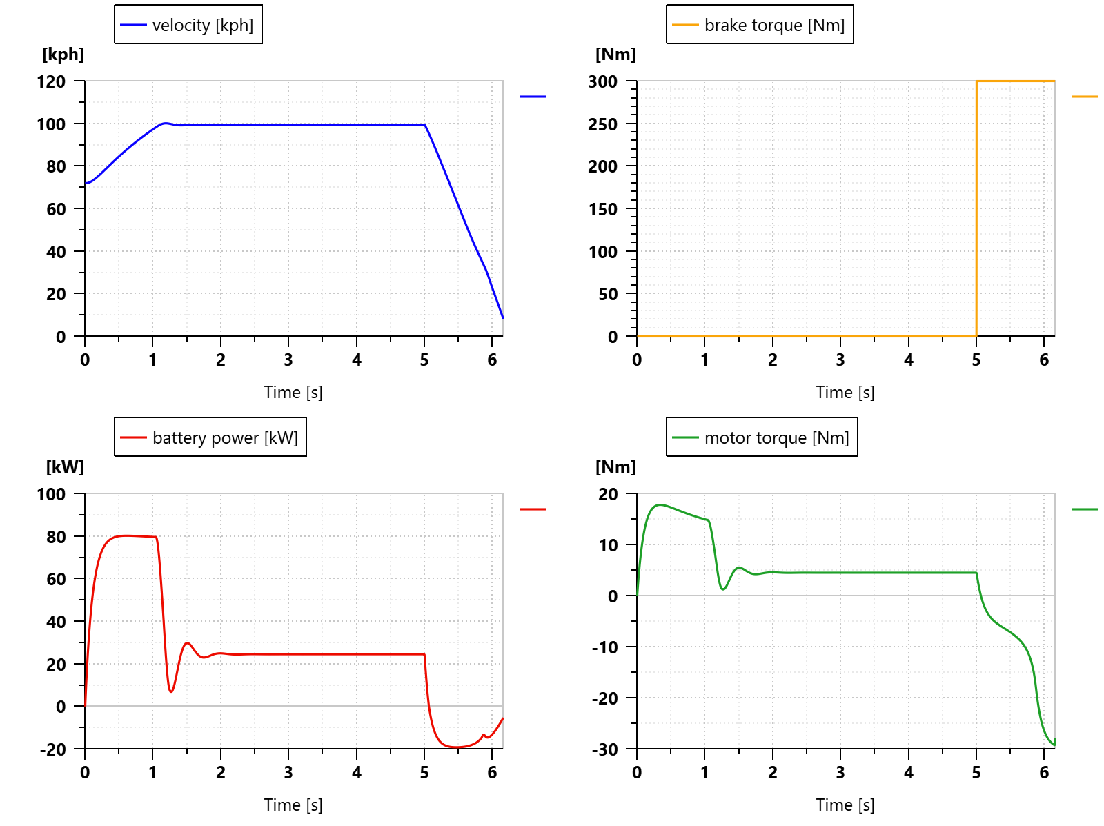
To design the controls for two different braking strategies and to verify that the maximum recuperation power is not exceeded, the maneuver analyzer is utilized. We choose the maneuver “Steady brake command”. A starting velocity of 100 kph is specified.
The velocity plot shows the vehicle accelerating to the starting velocity and then hitting the brakes at five seconds. Below are the front left motor and brake torque, respectively, followed by the battery power. During the maneuver, the brake pedal is fully pressed down, meaning that the mechanical brake is providing maximum braking torque. The controls limit the braking torque of the motors so that the recuperation power limit of the battery— 20 kW in this case — is not exceeded.
Having verified the functionality of the controls, we can move on to simulating a full lap on the racetrack. To do this, we simply switch the driver model and supply the track file and corresponding velocity profile, and the simulation is ready to be started.
Let’s assume that we have three different battery cells available for selection, each allowing a different maximum charging current. This will result in a different maximum recuperation power of the battery, as it is the product of the maximum charging current and the battery voltage. The total battery voltage is restricted by the requirements of the electric motors and inverters, as well as Formula Student regulations. Assuming that we have already determined the voltage our battery needs to provide, a cell with a higher maximum charging current will make a higher maximum recuperation power available.
Furthermore, we can choose from two different braking strategies, which have been implemented in the controls:
- Parallel braking: When the brake pedal is pressed, the mechanical brakes and the recuperation braking are activated simultaneously.
- Series braking: When the brake pedal is pressed, the first section of the travel solely activates the recuperation braking through the motors. The mechanical brakes are only actuated after a certain amount of travel, e. g. 50%.
To assess all combinations of these options, a batch study is set up in the Study Manager in Simcenter Amesim. This yields the following design matrix:
| Run | Max. recuperation power [kW] | Braking strategy |
|---|---|---|
| 1 | 20 | Series |
| 2 | 20 | Parallel |
| 3 | 30 | Series |
| 4 | 30 | Parallel |
| 5 | 40 | Series |
| 6 | 40 | Parallel |
Then, we start the study, automatically executing the simulation runs. To evaluate the different configurations, we compare several metrics regarding energy usage and heat output of the battery and motors. This is the state of charge of the battery over one lap:
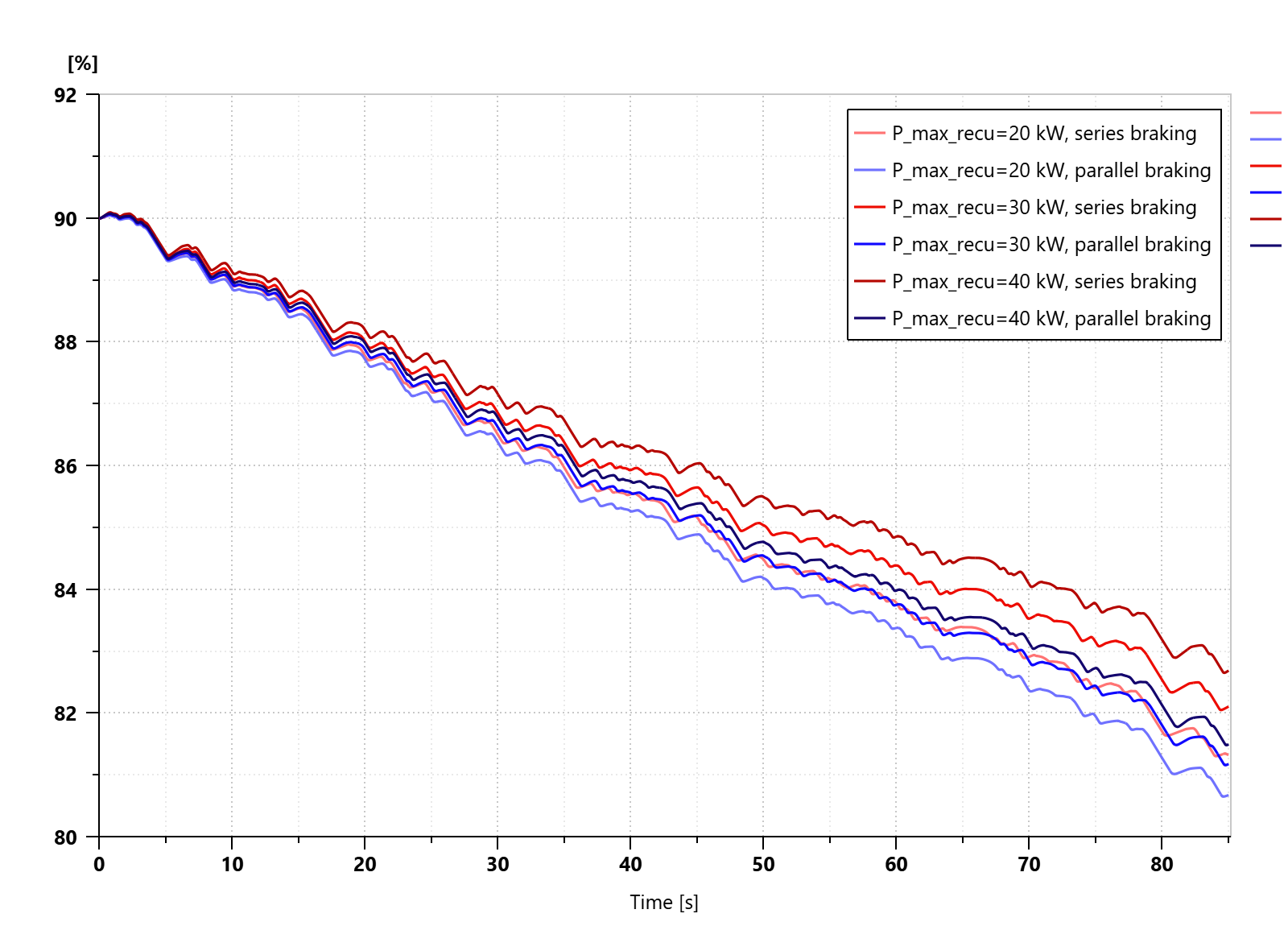
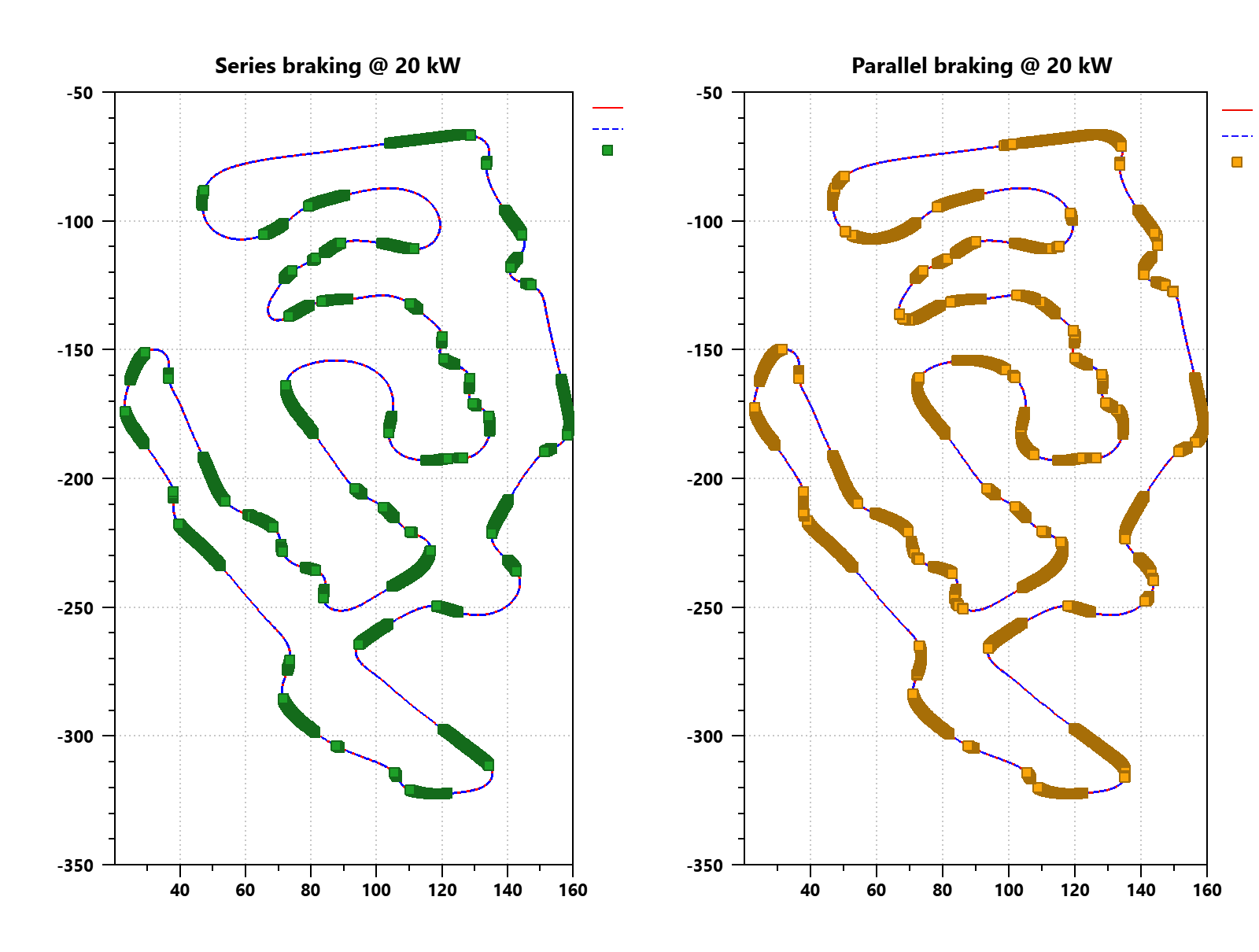
As expected, the higher the recuperation power, the less the battery is depleted. The braking strategy seems to have an even bigger impact on the state of charge. The following plot shows the sections on the track where the mechanical brake is being used for a recuperation power of 20 kW and series and parallel braking. As can be seen, the mechanical braking zones are larger for the parallel braking strategy.
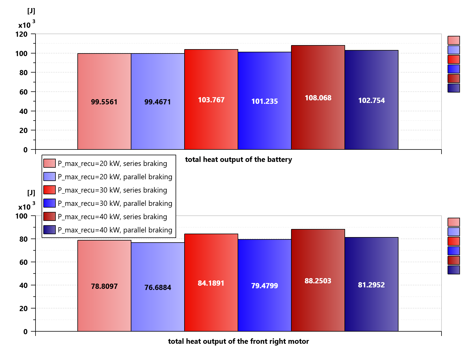
The tradeoff is that with higher recuperation power and more frequent usage of the motor brake, more heat will be generated, thus increasing the requirements for the cooling. The following plots show the total heat being generated over one lap by the battery and one of the motors.
Aerodynamics and suspension interaction
Having completed this early-stage analysis of braking strategies, we are now going to look at another example from a later stage of the development cycle. An important aspect of racecar development is the interaction between the aerodynamics and suspension.
While driving around the track, the car changes its attitude (roll angle, pitch angle, ride height, sideslip angle), which affects the aerodynamic properties of the car. To be able to investigate this interaction, it is not enough to characterize the aerodynamics of the car with constant drag and downforce coefficients, as was the case up to this point. Instead, a different submodel of the aerodynamic component is chosen, which allows us to apply an aerodynamic map to the car. This map defines all aerodynamic forces and moments acting on the car depending on its attitude. Most commonly, this data is obtained by performing CFD simulations of the car in different attitudes.

To closely examine the behavior of suspension and aerodynamics in one scenario, the maneuver analyzer is again utilized. The maneuver “Braking in a turn” is chosen, in which the vehicle first drives into a corner with a constant steering wheel angle and then hits the brakes while keeping the same steering angle. The following plot shows the vertical force on each tire for the given vehicle.
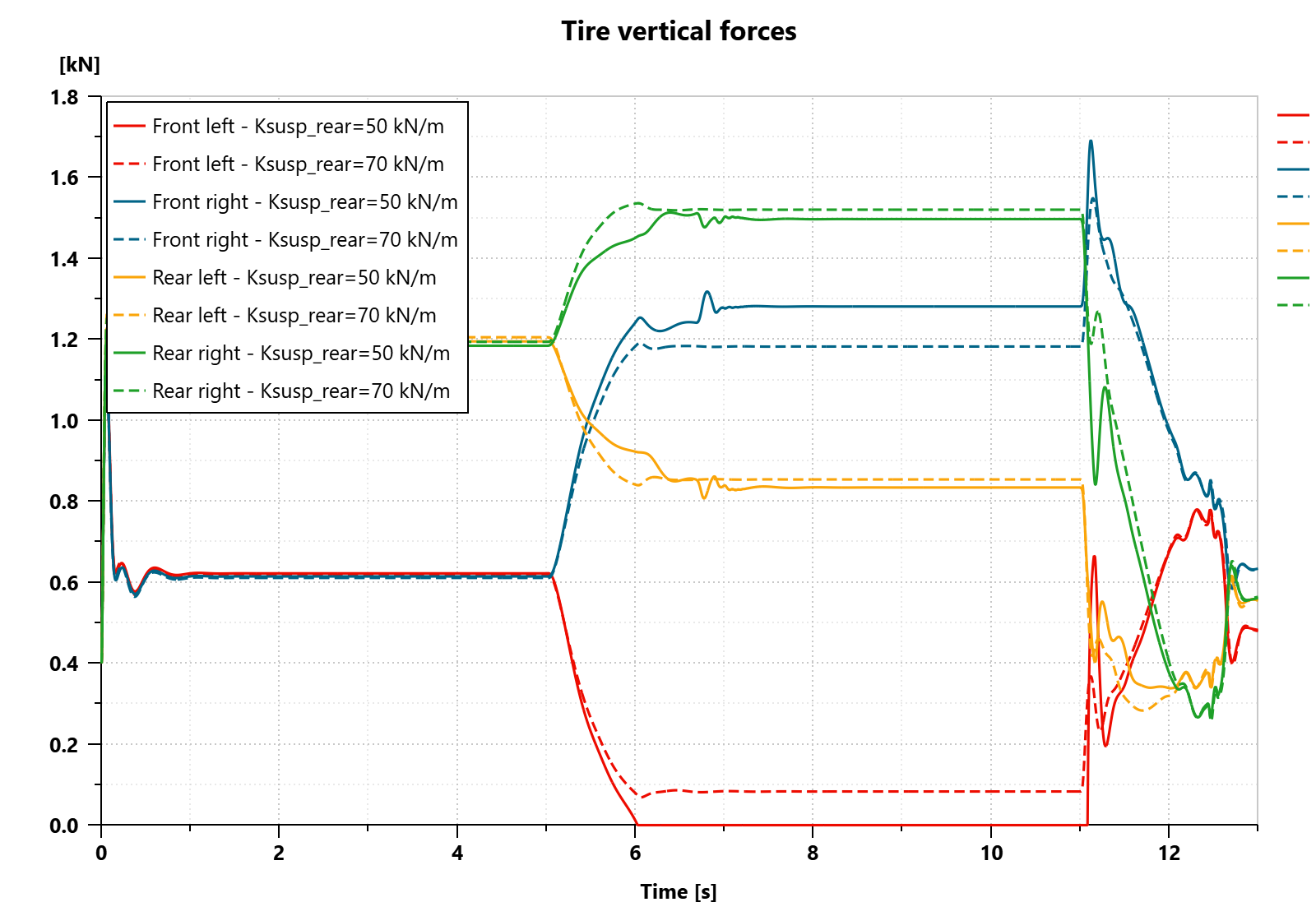
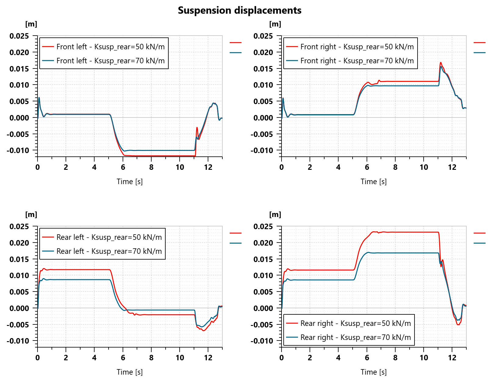
The front left tire has zero vertical force during the steady-state cornering (from 6 to 11 seconds) and then a large spike in its vertical force when the braking maneuver starts. This is not desirable, and to counteract this, the stiffness of the rear suspension is increased. The result can be seen in the dashed lines. By increasing the rear suspension stiffness, we were able to decrease the load transfer on the front axle, bringing the front left tire into firm contact with the ground again. Additionally, the suspension displacements are reduced, decreasing the roll and pitch angles, and thus keeping the car attitude in a better range for the aerodynamics.
Conclusion
We have seen that, with the Formula Student template model, any aspect of the vehicle can be analyzed easily and quickly, while taking all important interactions into account.
The three key benefits of using Simcenter Amesim for the model-based development of a Formula Student racecar are:
- Make critical decisions with confidence.
- Speed up your development process and go through more design iterations.
- Ensure that all components of the car work well together and fulfill the overall goals.
Watch the video below for a step by step demo of the feature:
The model is available to all Simcenter Amesim 2404 users in the Race cars section of the Chassis demo library. More features released in Simcenter Amesim 2404 are described in this blog.