Beyond lubrication: Unveiling thermal coupling in Simcenter STAR-CCM+ SPH

Mention oil and most people will think about friction, after all if you want something to move freely then you add oil to the surfaces. When we think about oil in cars, most people will think about engines, gears and their smooth operation. But oil has dual benefit: by virtue of its high thermal conductivity and high specific heat capacity it makes a very effective coolant. Whether that’s the cooling jets stopping piston crowns from melting, the gearbox oil carrying away the waste heat from a gear mesh, or oil sprayed onto eMotors.

Simulating these applications of oil with CFD is challenging, and while Simcenter STAR-CCM+ allowed to tackle those through Hybrid Multiphase for quite some time, this can be a computationally relatively costly endeavor, especially in early design phases. With version 2606 Simcenter STAR-CCM+ adds a massive leap in capability to the Smoothed Particle Hydrodynamics (SPH) solver so that you can iterate faster without losing fidelity. As a key leading application, in this blog we will focus on the vital role oil plays in electric motors.
Understanding heat generation in electric motors
Electric motors convert electric power to mechanical power incredibly efficiently (94 percent or higher) but losses still exist. A 200kW EV motor loses approximately ~12kW, mostly as heat. What exactly happens if we don’t manage that heat properly? High temperatures are particularly bad for the windings. Copper’s resistance increases with temperature, leading to increased energy losses and further heat generation. The winding insulation also has a thermal rating, and exceeding it leads to premature degradation. The flux density of permanent magnets also reduces with temperature, impacting torque output.
The heat originates from two primary sources: Joule losses in the windings and iron losses in the core. Joule losses occur when current flows through the motor windings.
Because these losses are proportional to current squared, they can rapidly escalate. To mitigate this, there’s a growing trend toward higher voltage architectures (400V or 800V), which reduce current-related losses—though this comes at the cost of significantly more expensive components.
Iron losses, meanwhile, result from both eddy currents and hysteresis in the stator and rotor cores. Eddy currents are induced electrical currents within the magnetic core that oppose the original change in flux, leading to energy dissipation as heat. Hysteresis losses occur as the core material continuously reorients itself to follow the rapidly changing magnetic field direction, with the energy required for this reorientation also converting to heat. Finally there are also small friction losses from the bearings and rotor movement.
Keeping our cool, efficiently
Now that we’ve learned where the heat comes from and all the problems it can create, what can we do about it? In practice, whilst a simple motor like an alternator can be air-cooled with an open back design, EV motors rely on liquid cooling to keep temperatures under control. Water-glycol jackets operate in the same way as those in a cylinder head and water has a much higher thermal conductivity and specific heat capacity than oil. However, as oil is dielectric it can be sprayed directly onto the hottest parts of the motor, making it an order of magnitude more effective than a water jacket. Gear oil is also convenient to use as it can additionally lubricate the bearings and other transmission components in an Electric Drive Unit (EDU).
The perfect solution then? Well, the continuous strive for drivetrain efficiency demands lighter weight: less system mass means less energy required to accelerate and decelerate, lower overall power consumption and key for most buyers: a higher range figure. Increasing the system power density means proportionally less material, which means less heat capacity and less thermal inertia, the hottest parts get hotter faster, with no ability to act as a sink and distribute the heat. This places increasing demands on the cooling system to absorb and distribute heat.
Unfortunately, lightweighting applies to the oil volume too. Reducing the volume of liquids also reduces dynamic mass (great!), but at the cost of cooling system capacity. This means that engineers need to make sure that every precious drop of coolant is used as effectively as possible to extract maximum performance from the cooling system.

If we consider a thermal abuse loadcase where the motor is outputting high torque and low power (imagine driving a heavily laden vehicle up a steep hill), the aim is to identify areas starved of coolant and also predict the overall rise in system temperature. If we focus on spray cooling as is typical in most current generation EVs, various configurations of stationary and rotating jets are employed to cool the end windings. However, the challenge is that the time scales of flow and thermal phenomena are very different, whilst we might be resolving details of the oil jets in the order of milliseconds, reaching thermal equilibrium can take minutes.
SPH and thermal simulation – coupled physics made easy
SPH is a wonderful tool for capturing violent oil flows in drivetrains. I’ve spent 10 years doing just that for everything from construction machinery to racecars. Capturing the fluid-thermal interaction adds another layer of complexity. Typically solving this problem with SPH simulation relied on either simulating a short duration and then extrapolating the heat transfer over time, or mapping between separate simulations, with manual export of Heat Transfer Coefficients (HTCs) each time the data is exchanged. This might be OK for a handful of simulations, but it becomes tedious and error prone when trying to do it for a full design study. It’s possible to improve the situation with some script stitching, but these days shorter EV development times are seen as a competitive advantage. There has to be a better way.
Simcenter STAR-CCM+ 2606 addresses this challenge by enabling the SPH solver to couple directly with the Simcenter STAR-CCM+ Energy Solver for conjugate heat transfer simulation. You now have access to the advanced physics and boundary conditions available in the Energy solver alongside your SPH simulation in a single environment. This allows full modelling of the fluid temperature evolution, heat transfer at the walls and solid temperature evolution in a fully coupled simulation. Both simulations are set up in the same Simcenter STAR-CCM+ environment for a familiar and consistent workflow.


Comparison of convective Heat Transfer Coefficient as a function of inlet velocity between Simcenter STAR-CCM+ SPH and experiment. Source Kekila et al, 2019, NREL/CP-5400-74284
Alternatively, Simulation Operations can be used to stagger the fluid and thermal simulations and capture longer timescales. What would have required scripts can now be done easily in a few clicks in Simcenter STAR-CCM+ SPH. This capability delivers more reliable predictions for cooling simulations, eliminates manual data transfer and allows seamless post-processing without needing to switch tools.
Extending SPH with multiphysics and coupled thermal-electromagnetics- CFD
Remember those iron losses we talked about earlier? It’s typical to assume that these are constant in a thermofluids simulation, when in fact they are strongly coupled with temperature. My colleague Andrea Matrisciano describes oil-cooled e-motors wonderfully as “a small multidisciplinary ecosystem with a rotating shaft”. He has a fantastic blog post on the recent updates in Simcenter STAR-CCM+ which make the EMAG solver easier to use than ever.
Normally if we wanted to capture this effect it would involve a complex mapping procedure between separate tools, in Simcenter STAR-CCM+ we can activate the electromagnetic solver and add it to our Simulation Operations loop. This gives us the ability to update the losses given our new temperature distribution as the oil propagates and the temperature evolves, all internal to Simcenter STAR-CCM+.
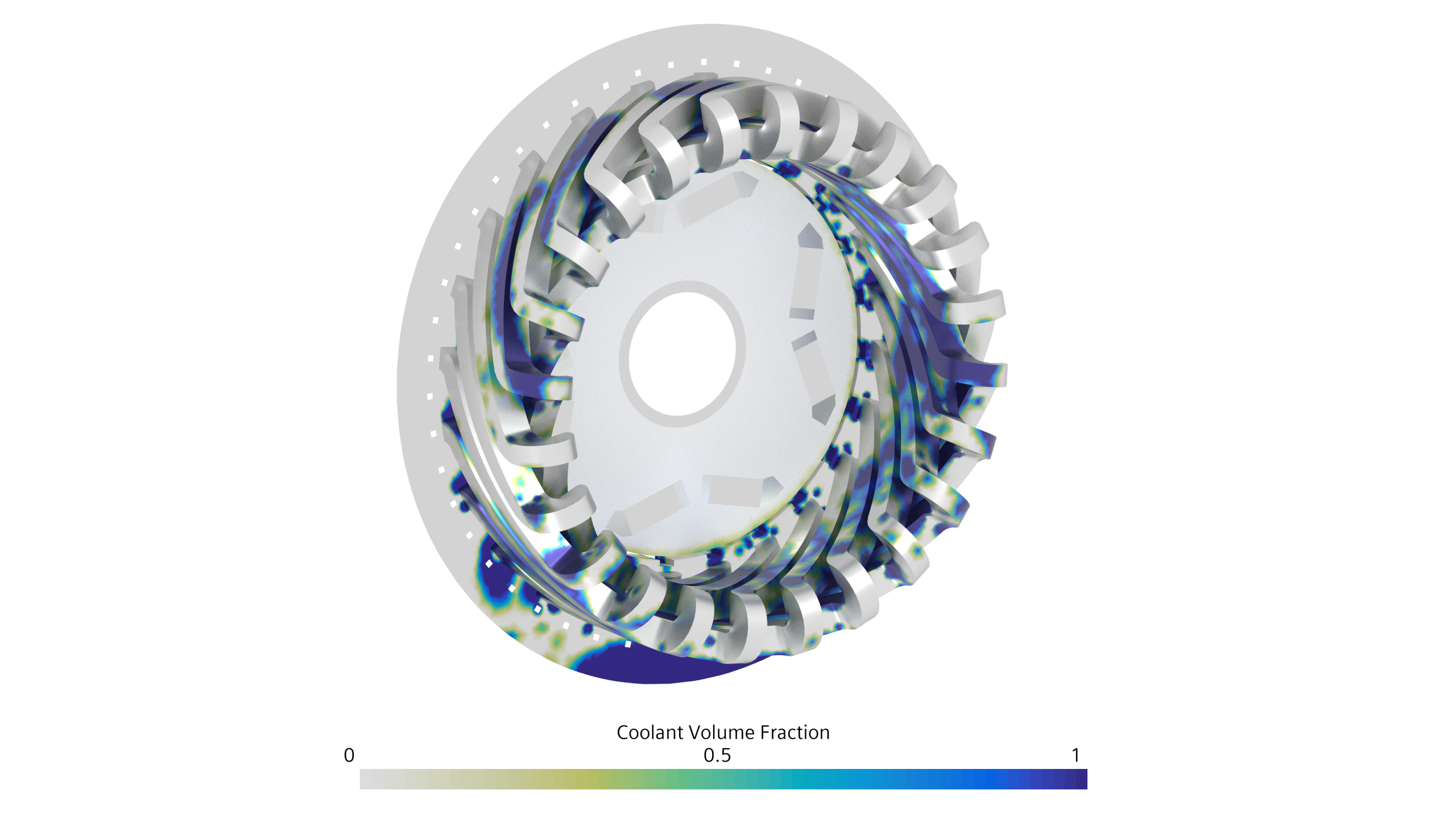

Asymmetric cooling oil distribution is driven by the winding angle and the resulting impact on cooling (HTC). Individually aligning the outer oil jets is one way to solve this problem, a task made much easier with optimization.
So now we have a simulation which captures the coupled effects of the problem. In the opening, we said we had to use oil as effectively as possible to extract maximum performance from the cooling system. Now as an engineer, we can look at the results and change the number of jets, location, jet diameter and angle to optimize the wetting of the windings and maximize heat transfer. With a meshless approach to the fluids simulation these kinds of changes are much simpler to make and iterate through. We can also use Simcenter HEEDS to make these changes automatically in a study and optimize the wetting behavior for us. Our partners at InDesA presented just this approach at Realize Live Europe:
Simulation should go beyond the oil
Whilst we have focused on electric motors here, it doesn’t matter what engine is propelling your vehicle, it’s efficiency and reliable performance is dependent on oil. Making sure that our design gets enough oil to the right places in sufficient quantity to prevent a system failure relies on simulation. Making accurate predictions requires tightly coupled flow and energy solvers. Making those predictions quickly enough to keep up with the design cycle requires seamless integration and built in optimization capabilities.


